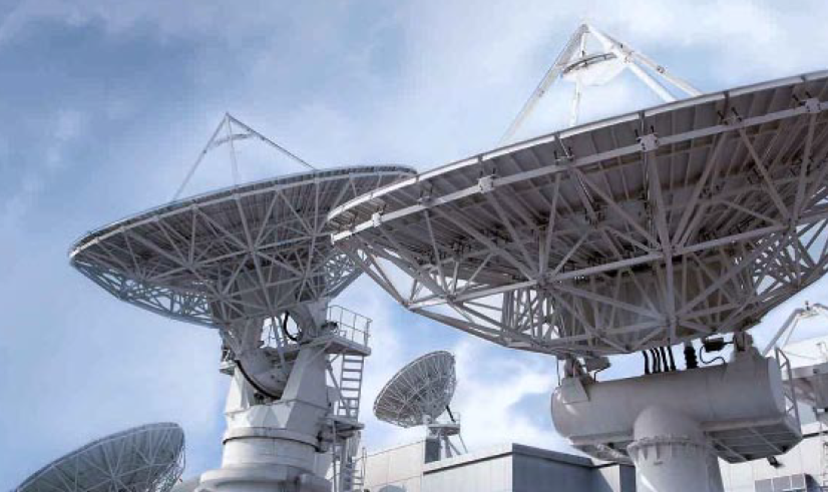
AsiaSat’s Tai Po Earth Station.
Higher data rates, ultra-low latency and massive machine-type connections, these are some of the promises of the fifth generation (5G) mobile communication that have caught tremendous media attention.
In order to make 5G possible, mobile operators have taken up a number of different frequency bands, including C-band spectrum, which has been used by satellites for over five decades. In a number of countries and regions, some portions of C-band spectrum have been seized upon by mobile operators to “kick-start” the 5G commercial deployment.
However, as we should argue, C-band is not the correct band to support the key performance indicators (KPIs) that are promised by 5G.
For decades, the use of satellite has complemented landline infrastructure to connect the world’s underserved regions, with C-band spectrum being used by GEO communication satellites to provide comprehensive coverage over a continental-wide footprint. The current C-band 5G network deployment amounts to only a transitional phase for the mobile industry, however it has significantly disrupted the existing C-band satellite services.
To understand the interplay between 5G and satellite communications, we should first look at whether all the talks about using C-band 5G to unlock the benefits of 5G is as good as it seems.
We have selected two of the key 5G KPIs, user experienced data rate and latency for a closer look. The other 5G KPIs are shown in the radar chart of Figure 1, including peak data rate, spectrum efficiency, mobility, connection density, network energy efficiency and area traffic capacity [2].
5G KPI — User Experienced Data Rate
It will be shown that operating a 5G network using C-band cannot achieve the user data rate KPI — not even by a long shot. The 5G user experienced data rate KPI of 100 Mbps (as shown in Figure 1) can be achieved on simulations or tests under ideal conditions, e.g., single user, with no inter- or intra-sector beam interferences [3] [4].
However, if the number of beams (inter-beam interference), available bandwidth, antenna and RF power performances are counted in the simulation, it can be found the realizable data rate will be far less than expected when the number of users increases. Evidently, much wider bandwidth at a much higher frequency than the C-band spectrum must be used to reach the KPI goal.
In this simulation, we try to estimate the average throughput per user that a 5G active antenna system (AAS) can deliver to the end users when multiple beams generated by the AAS uniformly populate the desired coverage sector. The factors to be taken into account include a total 100 MHz C-band spectru m, 64T64R AAS with 200 W total output power, inter-beam interferences, and the gradually increased number of users served by the multiple beams formed by the 5G antenna array.
A typical 5G 64T64R C-band AAS array elements distribution is shown in Figure 2(a). The digitally-formed single beam without steering is shown in Figure 2(b) where the highlighted angular range is the targeted 5G coverage sector.
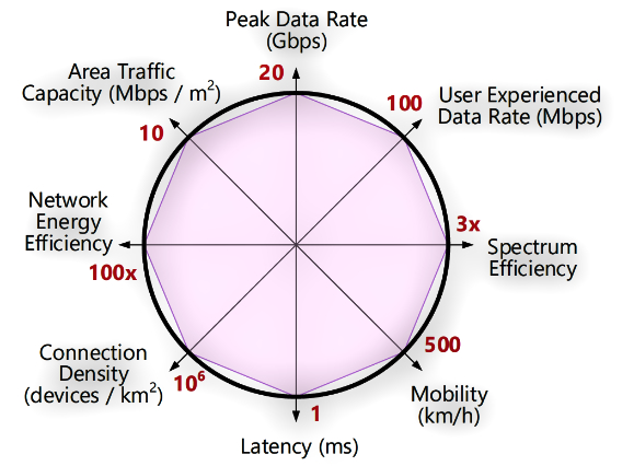
Figure 1. 5G KPI radar plot [1]. Source: ITU, IMT
Vision – Framework and overall objectives of the future
development of IMT for 2020 and beyond 2015
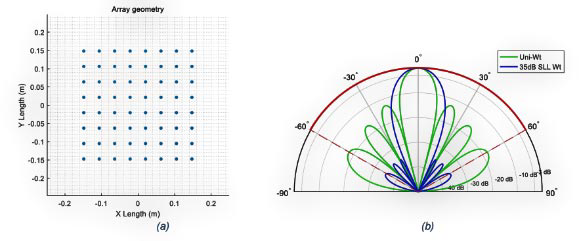
Figure 2. The 64T64R 5G AAS (a) array elements distribution, and (b) the formed single beams (array factor) using different side-lobe weighting. The highlighted 120 deg angular range is the targeted 5G sector coverage. Click to enlarge.
Applying different digital beamforming (DBF) weightings to the array elements, the beam side-lobe levels (SLL) as well as beam nulls can be controlled to reduce the co-channel interference to other users. The digitally-formed beam can be electrically steered in azimuth, elevation or both directions.
Besides, the phased array can also form multiple beams for one or multiple users at the same time. However, when the number of simultaneous beams increases, the inter-beam interferences can become severe and may degrade the link performance.
The simulated throughput per beam vs the number of simultaneous beams is shown in Figure 3, where it can be seen more than 450 Mbps per beam can be achieved when the number of beams is small. When the beam number increases, the throughput per beam will drop significantly to 50 Mbps or lower due to interference and the limited resources (e.g. power, bandwidth and time slot) allocated to each beam / user.
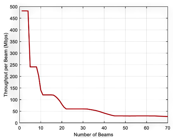 Figure 3. Throughput per beam vs. number of beams simulation.
It can be found the user experienced data rate KPI of 100 Mbps can only be met when there are fewer than 18 simultaneous users (assuming one beam serves one user) to fully load the base station capacity. It has to be mentioned the data rates achieved in this simulation are still the ideal values. In real situation, there must be other interferences and losses such as inter-sector interference, intermodulation interference, adjacent channel interference, channel fading, clutter loss and penetration loss that may further lower the achievable individual user data rate.
The best way to achieve the KPI of 100 Mbps for practical use of 5G is to increase the user bandwidth. Obviously C-band, like the other low frequency band used by the existing 3G and 4G networks, does not have the bandwidth to accommodate such needs/requirements. However, if we move to mm-wave (e.g., f = 26 GHz) or higher bands, the available spectrum can be increased by several times or more and the data rates can also be increased by several multiples [3] [4].
The relatively higher propagation loss at mm-wave band can be compensated by the reduced coverage range and the increased gain of array antennas packed with more elements on both the base stations and the end user terminals. Thus, by choosing to use a much smaller wavelength at a higher frequency band, 5G base stations can be designed to be much smaller, easier for massive integration and deployment. It could be just like the path of 4G deployment, where the number of coverage cells gradually increases while the cell radius is reduced from tens of kilometers (macro cell) down to tens of meters (pico- or femto-cell), aiming for much better user experienced data rate.
On the other hand, a satellite can accommodate a variety of data rate requirements of the end user terminals, including burst data rate, time-averaged data rate and sustainable data rate.
Burst data rate is best used for sensing and exploration applications, e.g., Internet of Things (IoT), oil and gas prospecting, LEO satellite Earth Observations (EO), where the data transmissions from the remote sensors to the hub station are in short bursts within a relatively long period. The transient data rate requirement can be medium to high, but the total data volume is low.
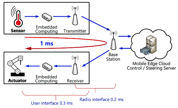 Figure 4. Factory automation industry communication latency illustration [5]. Source: ITU, The Tactile Internet, ITU-T Technology Watch Report, 2014
Time-averaged data rate describes common consumer communication applications, such as internet browsing, messaging, etc. In these applications, not all users send or receive data at the same time. Some fluctuation in waiting time is acceptable, thus the data rate requirement is defined in a time-averaged manner.
Sustainable data rate describes data intensive applications, such as video streaming and backbone network trunking, where the actual data transmission rate is constant over time.
For a satellite network, the aforementioned data rate requirements can be met by different access configurations. For example, single-carrier per channel (SCPC) can be used to handle sustainable data rate applications while TDMA configuration can properly handle the burst data applications. Moreover, satellite is specialized in broadcasting, and it can distribute TV, videos and other real-time information efficiently to a large number of users which is difficult to be achieved by a cellular network using data streaming.
5G KPI – Latency
For most applications, the end-to-end (E2E) latency performance is not dominated by the first link of the communication network, but the entire communication chain between the user and the application server. Therefore, the 5G latency of 1 ms in the KPI radar chart (shown in Figure 1) is highly misleading.
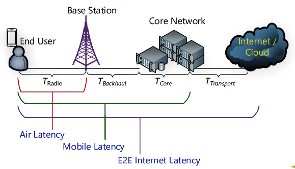 Figure 5. A typical 5G latency component illustration [6]. Source: IEEE, A survey on low latency towards 5G: RAN, core network and caching solutions, 2018
1) In fact, 1 ms represents the 5G requirement for the ultra-reliable and low latency communications (URLLC) application air latency TRadio, which is the delay between 5G radio access network (RAN) air interfaces of the base station and the user equipment [2]. Such an example is illustrated in Figure 4, where both ends (the sensor and the actuator) are located within the coverage of the same 5G base station.
2) TRadio includes the radio signal air propagation time and the physical layer processing time, e.g. time for channel coding, cyclic redundant check (CRC) attachment, modulation mapping [5], but does not take into account other delays in the communication chain, which amounts to only a tiny fraction of the total E2E latency. In other words, 5G simply cannot bend the physical law of signal propagation and reduce the lagging of the entire communication path, such as the path between USA and Hong Kong, to sub-millisecond level.
5G can only improve the latency within the mobile network. As illustrated in Figure 5, E2E internet latency T, the total time to bring an end user data packet to the destination application server, is contributed by different latency terms:
TRadio + TBackhaul + TCore +TTransport [6]
The first three terms add up to the mobile latency, which is dictated by 5G network. TRadio is the Air latency. TBackhaul is the time for building connections between the 5G base station and the 5G core network. Generally, fiber is used for this connection and the latency can be higher than those connected by microwave links. TCore is the 5G core network’s processing time consumed by mobility management entity (MME), software-defined network (SDN) and network function virtualization (NFV), etc. Finally, TTransport is the delay to data communication between the 5G core network and the application servers on the internet / cloud. Generally, TTransport is dictated by the conditions of the external networks, such as the distance between the
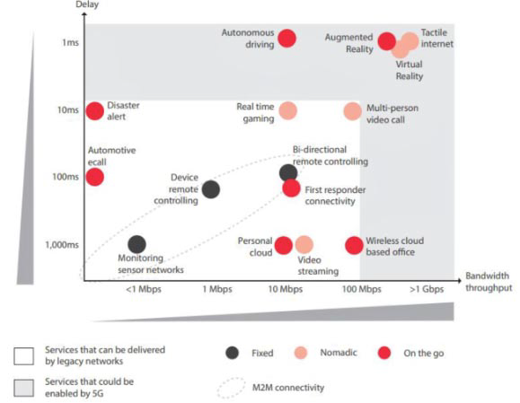 Figure 6. Different use cases and their needs for speed vs required latency [7] Source: GSMA Intelligence, Understanding 5G: Perspectives on future technological advancements in mobile, 2014
5G core network and the external server, bandwidth and communication protocols used. The E2E internet latency for general internet applications can vary from a few tens of ms up to seconds, while the mobile latency can be several to tens of ms for the existing LTE system.
Most 5G use cases can tolerate the overall latency (E2E internet latency) of the existing communication networks. Only a few specific applications require ultra-low latency, but not all of them can be benefited from 5G.
For example, the autonomous driving and factory automation industries whose communication latency is dominated by the mobile latency (see Figure 4) may thank 5G for the reduced latency that helps to meet the stringent sensing and responding delay time requirement. On the contrary, the communications for high frequency trading (HFT) business may see no difference using 4G or 5G, since the low latency it requires may not be dominated by the mobile network.
The other common internet applications such as messaging, video chatting, internet browsing, music and video streaming, are all unsusceptible to mobile network latency. The typical latency vs data rate requirements for different applications are compared in Figure 6, where most applications can be served with the legacy mobile network except for augmented reality (AR), virtual reality (VR) and Tactile internet applications on the upper right corner of Figure 6 which require not only ultra-low latency but also extremely high data rates that must be resolved with a much wider operating bandwidth in a higher frequency band.
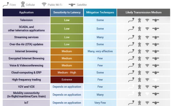 Figure 7. Latency sensitivity and the likely transmission medium of different applications [8]. Source: ESOA, Latency in Communications Networks, 2017
Traditional satellite communications can backhaul 5G network for most of its targeted applications. Unlike ground mobile networks, satellite networks exhibit relatively longer but stable latency.
As satellites have been used for communications for five decades, many matured methods have been developed to mitigate the latency effect in the two-way satellite data communications. The typical latency sensitivity and the likely transmission medium for different applications are compared and summarized in Figure 7, where it shows satellites can be used as the medium to carry traffic of most applications.
5G is often touted as a next-generation technology that will transform the world, which warrants taking C-band spectrum away from satellite-based applications. The real story may not be so simple.
First, the 5G KPIs may look attractive, but they can only be achieved with the deployment of higher frequency bands down the road. Looking at the history of mobile communication technology (as shown in Figure 8), it appears to take a whole decade or even longer to complete the handover from one generation to the next.
The reallocation of C-band spectrum seems to support the launch of 5G, but it provides only an incremental improvement over existing service and will not shorten the 4G to 5G transition.
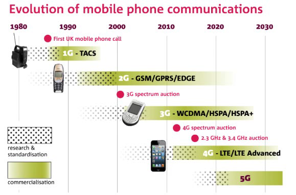 Figure 8 Mobile communication technology timeline in UK [9]. Source: Ofcom, Laying the foundations for ‘5G’ mobile, 2015
For realizing the KPI goals, the 5G network will eventually have to migrate to higher frequencies with much wider available spectrum. If it does not, 5G will turn out to be a wasteful investment with little benefits to the society.
Second, any direct comparison of spectrum use by satellite and 5G may be shortsighted and misguided because the benefits of C-band often extend beyond the borders of a domestic market. Satellite can complement landline infrastructure by bringing much-needed connectivity to the underserved regions. The current reallocation of C-band spectrum for 5G network amounts to only a transitional phase for the mobile industry, but it has disrupted the decades long of satellite communications.
Over the last 30 years, the satellite infrastructure provided by C-band has proven itself to be essential for providing broadcast and emergency communication services, which cannot be measured by the amount of revenues generated from the use of the spectrum [10].
Finally, the use of a GEO satellite for 5G backhaul ignores the point-to-multipoint ability of satellite to provide geographically diverse services and will not bring a sustainable business model to satellite industry. Providing reliable communications links, wide area coverages and significantly increased capacity per beam, a modern GEO satellite can serve many different business sectors across the world, with mobile backhaul being only one of them.
With today’s satellite technology, there is no doubt that a GEO satellite is capable of providing backhaul for partial or full-scale 5G data using wide or narrow beams. However, the extra satellite data traffic brought by the booming 5G business will have a short-lived impact — the demand will fade away as more landline connections become available.
www.asiasat.com
References
[1]. ITU, “IMT vision –Framework and overall objectives of the future development of IMT for 2020 and beyond,” Recommendation ITU-R, M.2083-0, Sep. 2015.
[2]. 3GPP, “Study on scenarios and requirements for next generation access technologies,” 3GPP TR 38.913, v15.0.0, Jun. 2018.
[3]. HTCL, “Test report for trial of 5G base station and user equipment operating at 26/28 GHz bands and 3.5 GHz band,” Mar. 2019. Available online at https://www.ofca.gov.hk/filemanager/ofca/en/con-tent_669/tr201904_01.pdf.
[4]. D. Morley, “Real-world performance of 5G,” Technical Paper for SCTE·ISBE, 2019. Available online at https://www.nctatechnicalpapers.com/Paper/2019/2019-real-world-performance-of-5g/download.
[5]. ITU, “The tactile internet,” ITU-T Technology Watch Report, Aug. 2014.
[6]. I. Parvez, A. Rahmati, I. Guvenc, A. Sarwat and H. Dai, “A survey on low latency towards 5G: RAN, core network and caching solutions,” IEEE Communications Surveys & Tutorials, vol. 20, issue 4, 2018.
[7]. GSMA Intelligence, “Understanding 5G: Perspectives on future technological advancements in mobile,” 2014. Available online at https://www.gsma.com/futurenetworks/wp-content/uploads/2015/01/Under-standing-5G-Perspectives-on-future-technological-advancements-in-mobile.pdf.
[8]. ESOA, “Latency in communications networks,” 2017. Available online at https://www.esoa.net/Re-sources/1527-ESOA-Latency-Update-Proof4.pdf.
[9]. Ofcom, “Laying the foundations for ‘5G’ mobile,” 2015. Available online at https://www.ofcom.org.uk/about-ofcom/latest/media/media-releases/2015/6ghz.
[10]. Euroconsult, “Assessment of C-band usage in Asian countries,” Jun. 2014. Available online at http://www.casbaa.com/publication/assessment-of-c-band-usage-in-asian-countries-2/.

