
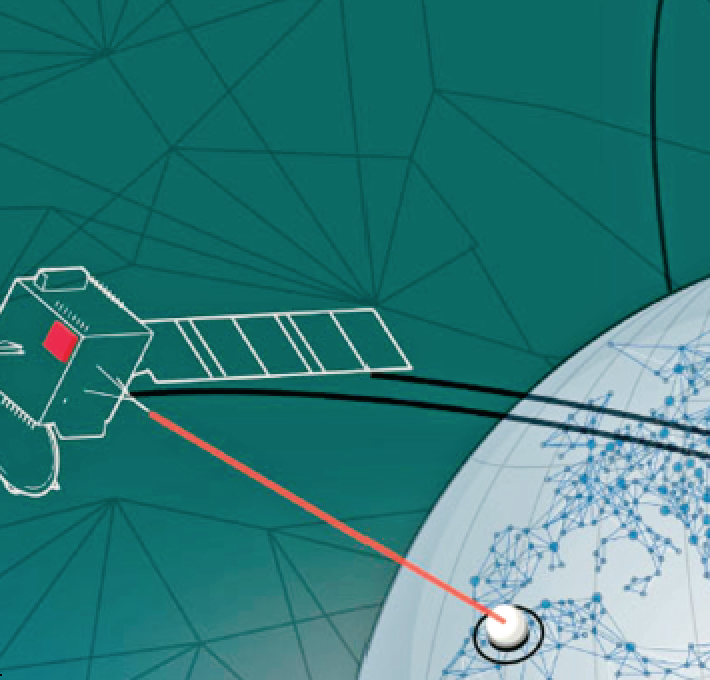
For operators that need to securely and efficiently move large amounts of data from space to ground, optical communications offer a viable solution.
Previous articles have discussed the history of optical communications (www.satmagazine.com/story.php?number=2026136812), as well as the benefits for smallsats and secure communications (www.satmagazine.com/story.php?number=1701251348)
(http://www.milsatmagazine.com/story.php?number=723110643).
Generally, commercial satellite operators understand RF systems much better than optical communications — this addresses the basics by comparing the two designs.
Data Rates of Optical versus RF Communications
The first step in evaluating the communications architecture for a satellite system is the trade between availability of spectrum and necessary data rates required for the specific mission. A summary of the typical options is shown in the table (Figure 1) on the following page.
Of course, the data rates shown in this table only tell part of the story.
First of all, the flight hardware, encoding and modulation scheme, ground stations, and link budgets need to support the assumed data rates. For RF systems, these options are well understood, so let’s focus on the optical communications system.

Design of Laser Communications Terminals
There are a number of qualified space hardware suppliers that are offering optical comms hardware, known as laser communications terminals (LCTs), in the data rates shown in Figure 1.
In addition to data rates, these manufacturers offer different levels of qualification, sizes, power consumption, encoding/modulation, delivery schedule and price. However, all these LCTs use similar design elements:
Modem or RF-to-digital converter
Before the data is encoded and modulated on the laser, it first needs to be converted into the digital domain from either a RF signal or from a mass memory storage device on the satellite. Once converted to digital, most LCT designs utilize an encoding scheme that will help overcome the noise and losses that primarily come from atmospheric effects. These schemes could include some combination of forward error correction (FEC), interleaving, and/or an automatic repeat request (ARQ). Encoding can lower the bit error rate (BER) substantially, but at the expense of additional overhead that effectively reduces the data rate. While there are a number of RF broadcast standards available (most notably Digital Video Broadcasting (DVB) S2), an optical communications standard is being developed by the Consultative Committee for Space Data Systems (CCSDS) optical working group (cwe.ccsds.org/fm/Lists/Charters/DispForm.aspx?ID=79).
Transmitter and Receiver, or Transceiver
Once the data is assembled with or without encoding, a seed laser, which is typically a stable low power laser diode, is modulated. The most simple modulation schemes are on-off keying (OOK), which changes the signal amplitude, or differential phase-shift keying (DPSK), which measures the change in the phase state. OOK and DPSK only offer one bit per symbol, but work with simple direct detection receivers. The more advanced modulation schemes that are common in the RF world, such as phase shift keying (PSK) or quadrature amplitude modulation (QAM), require coherent receivers that can more accurately measure amplitude and modulation changes.
Amplifier
Most LCTs use fiber amplifiers, which are optical glass fibers doped with rare earth ions such as erbium, neodymium, ytterbium, praseodymium, or thulium. This active dopant is pumped with light from a seed laser in the transmitter, which propagates through the fiber core and amplifies the signal. Most designs today use Erbium-doped fiber amplifiers (EDFAs) that have relatively low efficiencies (around ten to twenty percent), but can output up to ten or more watts of laser output power.
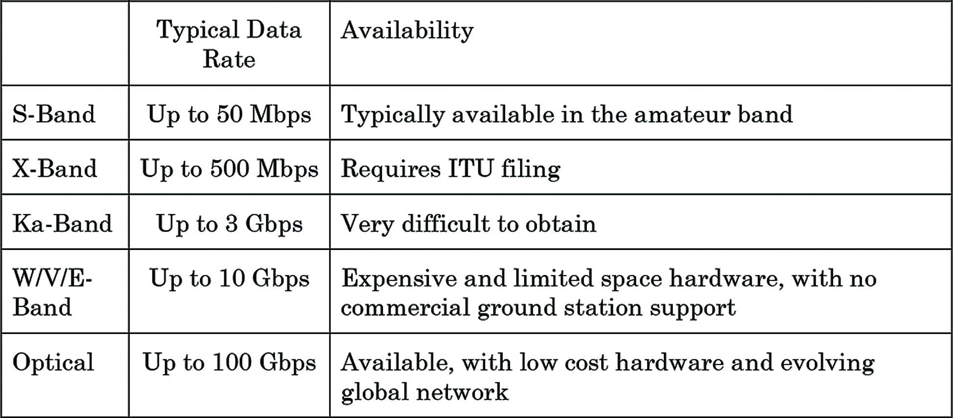
Figure 1.
Optical Head Assembly (OHA)
The most advanced technology for LCTs resides in the optical head assemblies, which contains the optics necessary to convert the laser signal into a beam that is transmitted and received. Some designs split the transmit and receive paths, but most use a more mass efficient co-boresighted design that requires filters and beamsplitters to segregate the two signals. The simplest OHA designs use an open-loop pointing system based on the spacecraft pointing knowledge, and therefore do not require active pointing and position sensing equipment. To achieve tighter beams with higher data rates, a closed-loop lock of a receiver beacon is required. The more sophisticated designs utilize steering mechanisms and passive isolators to compensate for satellite pointing errors and spacecraft micro-vibrations based on the feedback from the beacon
Controller, Power, and Command/Telemetry Interface electronics
To round off the list, these electronics are usually packaged as separate cards that are designed to interface with the LCT and the spacecraft.
Optical Communications Link Budgets
The data rate is found from the optical communications design and the associated link budget, which is similar to the traditional RF link budget.

The key differences between the two types of budgets is in the evaluation of the transmit and receive gain, and the transient atmospheric losses associated with scintillation and clouds. Otherwise, the terms in an optical comms link budget should look familiar: the amount of power collected by the receiver is proportional to the square of the transmit and receive telescope diameters, and inversely proportional to the square of the range and the optical wavelength:
The key parameters in the optical link budget:
Laser Output Power
Typically ranges from low milliwatts to single digit watts of output power, based on today’s best fiber amplifiers. Data rates (or, more accurately, the link margin) increase proportionally with laser output power, but so does DC power consumption on
the satellite.
Laser Transmit Beam Divergence Angle
This is set by the design of the transmit optics in the LCT, and defined by the transmit waist diameter. Narrower beams provide better link margins, but at the expense of more complicated pointing and tracking mechanisms.

Pointing Loss
This is located by considering the pointing accuracy of the beam against the beam divergence angle. All laser beams output power in a roughly normal (gaussian) distribution, so a small pointing error with a wide beam divergence angle would have lower peak power losses than the alternate. However, tight pointing angles require ever more sophisticated sensing/tracking and pointing mechanisms. Simple open-loop pointing systems can achieve around 1/10 of a degree of pointing accuracy based on the spacecraft, requiring half a degree laser beamwidth. Current state-of-the-art closed-loop designs have beamwidths that are less than 100 micro-radians, with pointing in the tens of microradians, yielding far better data rates (consider that data rate improves as a square of beam width).
Free-Space Optics (FSO) Loss
This a simple calculation based on the wavelength (typically 1550 nm) and range (typically 1500 km slant range for LEO satellites).
Atmospheric and Scintillation Loss
This most difficult term to properly assess, even though there are a large number of papers written on the subject (https://ntrs.nasa.gov/search.jsp?R=19890017910). There are localized atmospheric effects that mean that atmospheric losses fluctuate in time, as well as based on the elevation angle and altitude of the ground station.
Receiver Optics
Ground stations receive telescope apertures typically range between 40 to 60 cm diameter, though they can be larger. As the size increases, the cost of large lenses increase almost exponentially, and the complexity of the telescope motor increases — however, the power collected is proportional to the square of the diameter.
Receiver Loss
While the receiver optics induce some loss, the receiver design can actually have positive gain if it removes scintillation effects through adaptive optics or multiple apertures. Optical signals can be distorted due to local scintillation effects in the atmosphere, which is similar to the visual star twinkling effect. The ground station can correct out these aberrations, providing better links during the transient effects. However, these modifications add expense and complexity to the ground station.
Receiver Sensitivity
This the minimum signal level needed to distinguish the signal from the noise from the received laser beam. Most receivers are avalanche photodiodes (APD) that are tuned to provide an electrical signal for the maximum data rate modulation of the optical signal. There are more sophisticated heterodyne receivers that use a local oscillator (LO) source to more accurately detect the phase and amplitude of the optical signal. These designs, while more expensive and complicated, support coherent signals that deliver multiple bits per symbol, with the resulting increase in data rates.
Mission Analysis
Once the data rate is established, the operator needs to prepare a mission analysis to assess data downlink capacity. BridgeSat prepares a detailed mission-specific analysis, using LCT capability, link budget, data rate, satellite orbit, and BridgeSat’s optical comm ground network as inputs.
Complicating this analysis is the statistical variation in cloud cover at the ground station locations. To evaluate this, a detailed statistical model has been created using seasonal cloud variation.
For example, a satellite in a LEO sun-synchronous orbit at 500 km using a 10 Gbps optical comms system and BridgeSat’s initial ground station sites, can expect more than 2 TB of data downlink per day.
BridgeSat is locating ten optical ground stations at low cloud sites, many in areas near the poles to ensure coverage for polar orbits. This gives the operator confidence that their valuable data will be downlinked quickly and efficiently.
Conclusions
Optical communications offer a strong solution for commercial satellite operators that need to securely and efficiently move large amounts of data off their satellites.
With a basic understanding of the design and applications of optical communications, these operators can make the best system trade for their next satellite architecture.
http://www.bridgesatinc.com/