The HTS capacity growth will come from two types of systems: new larger, higher capacity Geosynchronous-Orbit satellites (GEO-HTS), Low Earth Orbit (LEO) and Medium Earth Orbit (MEO) satellite constellations (non-GEO HTS) that consist of many (hundreds up to thousands) satellites in multiple orbital planes providing full Earth or regional coverage.
Over the next decade, non-GEO HTS demand and revenue growth is expected to be stronger than GEO-HTS, but with a smaller starting point. GEO-HTS will still provide a large majority of global capacity and revenue through 2028. NSR projects that only about 14 percent of the total market will be through non-GEO systems in 2028, with the rest still carried by GEO systems.
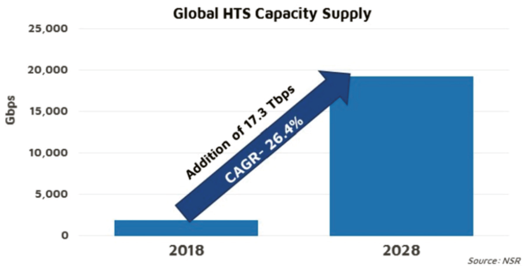
Figure 1. HTS/VHTS Capacity will grow to more than 20 Tbps by 2028.
These high-power amplifiers (HPAs) must provide at least 4.2 GHz of operational bandwidth with low gain and phase variation over the band and good linearity performance as measured using noise power ratio (NPR). They must also be compact, lightweight, and rugged to be capable of operation mounted very close to the feed to minimize loss.
The larger GEO gateway antennas can offer a lot of gain at such high frequencies, but the challenge of meeting pointing requirements at 50 GHz means that keeping antenna size down can help tremendously. It is the resulting cost tradeoff between antenna and RF high power amplifier that has driven a push to offer higher power amplifiers for this band.
Figure 2 on the following page summarizes the key requirements for the new V-band HPAs based on the current capability of 250W peak RF power. Higher power will be needed in the future, so additional TWTA development is taking place as well as offering phase combined systems using the 250W peak TWTAs.
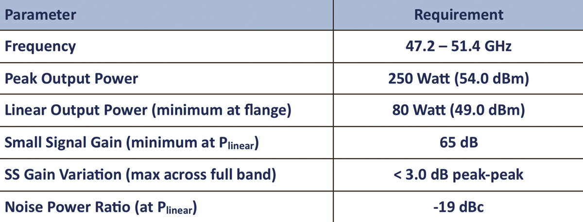
Figure 2. Key requirements for V-band gateway uplink amplifier
New traveling wave tube (TWT)-based amplifiers have been and are being developed for these applications, and the first of these has been delivered for system integration. This first commercially available Q/V-band uplink amplifier is a 250 watt peak TWTA providing 80 watts of linear RF power at the output flange as defined by an NPR of -19 dBc. The currently available unit weighing 58 lbs (26.3 kg) and drawing 1200 watts prime power is shown in Figure 3.
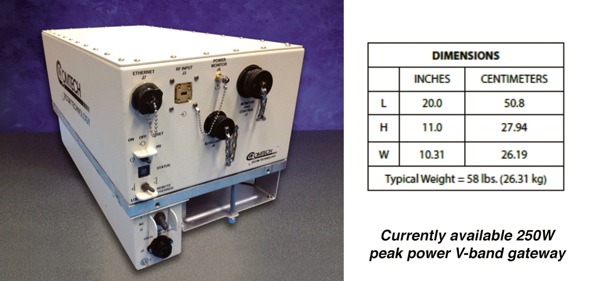
Figure 3. Currently available 250W peak output power V-band gateway uplink amplifier.
Some operators have been requesting even higher peak power and resulting linear power, while others are satisfied with the linear power provided by 500 watt peak TWTAs but would like to have SSPAs. Both are now feasible with recent developments.
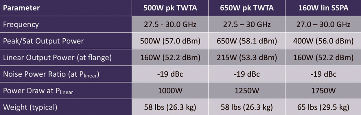
Figure 4. Ka-band gateway uplink TWTA and SSPA comparison.
For integrators who can meet their link needs with existing 500W peak power TWTAs but would like to begin transitioning to SSPAs, a new 160W linear Ka-band SSPA is needed.
The performance and physical difference between the existing 500W peak TWTA, the new 650W peak TWTA and the new 160W linear GaN SSPA is shown in Figure 4.
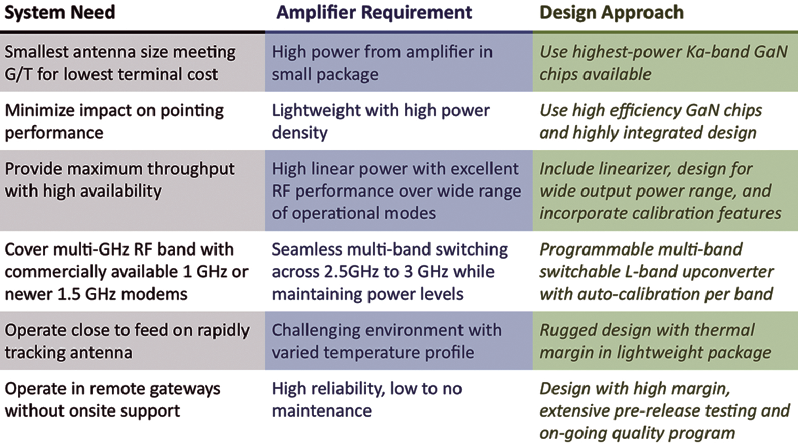 Figure 5. Key Ka-band SSPA requirements for new LEO systems.
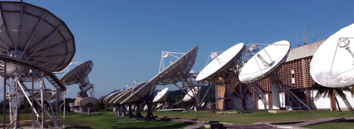
Gateway and user ground terminal approaches for the range of proposed LEO systems are myriad, but they all have much larger numbers of gateway and user terminals than traditional GEO systems.
New requirements, as compared with GEO systems, include horizon-to-horizon tracking antennas, complex new network management supporting rapid switching among many satellites and gateways, and lightweight, efficient, reliable and low-cost amplifiers that mount on rapidly tracking antennas at dozens to hundreds of gateways.
These SSPAs must provide 3 GHz of operational bandwidth with low gain variation over the band and good linearity performance as measured using noise power ratio (NPR).
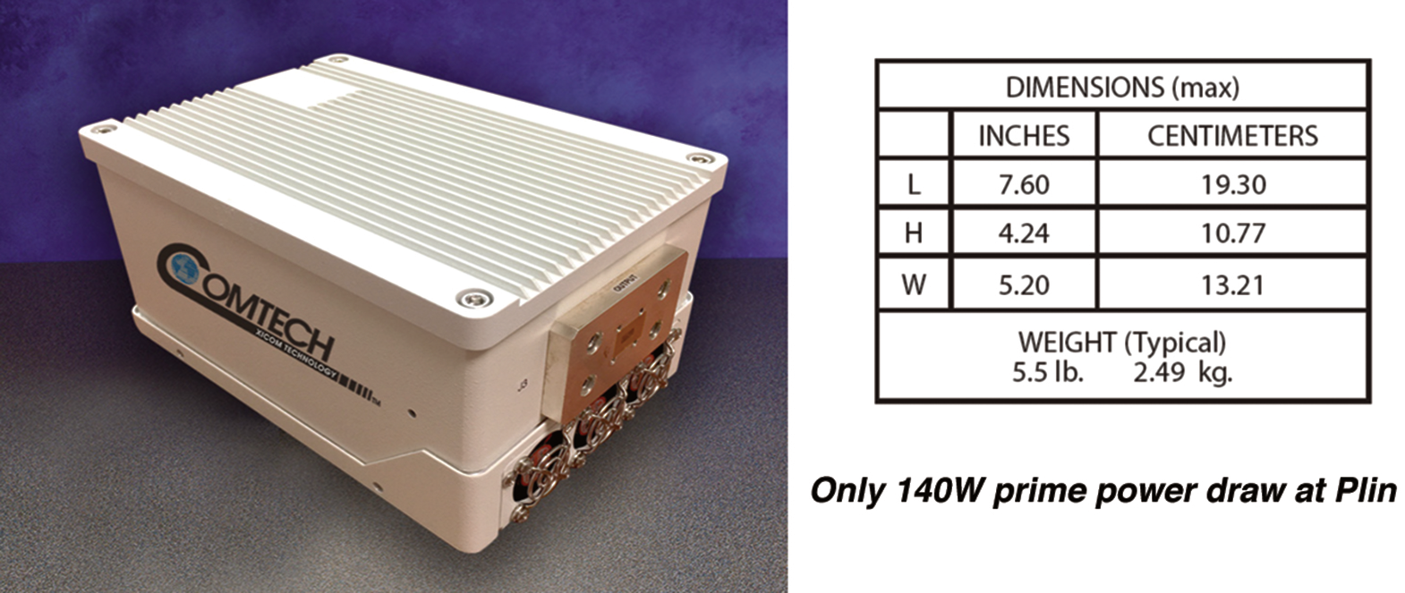 Figure 6. Ka-band 16W linear GaN SSPA for new LEO systems business users.
 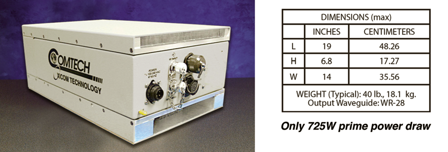 Figure 7. Ka-band 65W linear GaN SSPA for new LEO systems gateways.
They must also be compact, lightweight, and rugged to be capable of mounting on a rapidly moving platform close to the feed of the tracking antenna.
As with larger GEO gateways, the cost tradeoff between antenna size and RF amplifier power drives the need for higher power density while keeping weight and cost down.
Key requirements for the new Ka-band SSPAs must include the elements as shown in Figure 5..
A range of Ka-band SSPAs continues to be developed in the industry to meet these new requirements;
Comtech Xicom for example is offering a range of Ka-band SSPAs including linear power levels of 16W, 40W, 65W, 100W, and 160W. The 16W linear power (5.5 lb package) and 65W linear power (40 lb package) units are shown in Figures 6 and 7.
With rapid change occurring in the SATCOM industry, the demand for new and innovative amplifiers to address the requirements of operators and terminal integrators will continue and evolve for the foreseeable future.
The technology to support these is ready, and the SATCOM amplifier industry is working hard to use the latest technology to provide the best solutions for each system’s unique needs.

Heidi has her BSEE from Marquette University and MSEE in Communication Systems from University of Southern California.
V-Band Systems
SpaceX, Boeing, O3b, OneWeb, LeoSat and Telesat Canada (among others) have plans to launch over thousands of satellites for stand-alone V-band systems or as part of Ku- and Ka-band HTS systems with V-band payloads.
This will grow to more than 5 GHz if proposals to add 1 GHz of adjacent spectrum (51.4 - 52.4 GHz) are adopted at the next WARC. Initially, V-band will primarily be used to provide high capacity feeder links for Ka-band HTS systems, freeing up valuable capacity for users in beams where gateways are located.