For a number of years now, all realize that the data-rate for Internet consumers will need to support connectivity anywhere, any time, and for everybody.
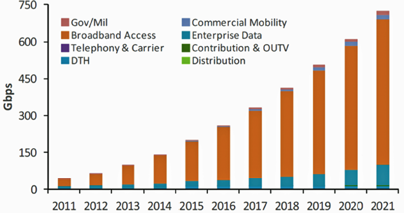
Figure 1. Forecast data demands
Smartphones, tablets and/or PCs are being used on the road in mobile applications as well as at home over Wi-Fi or fast broadband connections.
This demand is illustrated in the schematic of Figure 1 where the overall data-rate is forecast to increase by a factor of 2 (up to 600Gbps) over the next five years1.
Currently, terrestrial 3G and 4G telecom networks with one-and two-way satellite backhaul networks are implemented to cover the demand. However, the available data-rate is not enough, especially in the satellite segment.
As satellite networks have the great advantage of being able to provide cover quickly to any part of the world, this lack of data-rate is becoming more and more of an issue. That is why some companies that depend on full connectivity (e.g., Google, Facebook and Amazon), but are traditionally not involved in satellite technology, are seeking novel approaches to participate in the New Space sector. The satellite world/eco-system has to react to this growing data-rate demand; but how?
This article presents the current status of satellite architecture and the technology’s future technical evolution toward greater bandwidth and focuses on one particular solution—wideband operation as per Annex M, introduced in the DVB-S2X2 standard.
With 20 years of experience in digital modulation techniques for RF transmission, TeamCast presents their vision of the markets and the technologies associated with the evolution/revolution required by the satellite environment.
The Current Status
The current architecture for satellite transmission for broadcasting, DVB-S, has remained the same, ever since the introduction of the first digital transmission systems. This means that, since 1994, the architecture has been based on decomposing the 500 MHz typical frequency allocation of a satellite into ‘N’ 36 MHz transponders.
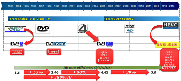
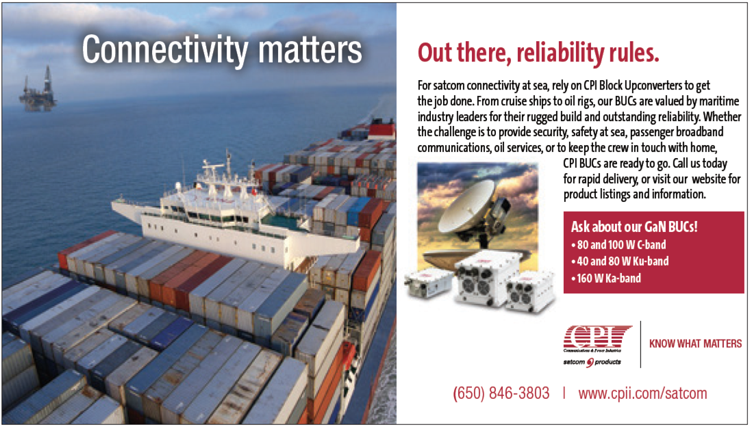
Figure 2. Standards efficiency evolution
Sometimes wider transponders with 54 MHz or 72 MHz bandwidth are available, but this is not common, mostly due to performance limitations of the on-board amplifiers. Based on this architecture, the efforts in recent years have mostly been to improve the spectral efficiency of the transmission which has led to many improvements of the standard: from DVB-S, to DVB-S2 and DVB-S2X. Figure 2 is an illustration of the efficiency evolution of these standards.
The Technology
The embedded technologies inside modulators and amplifiers make it possible to achieve the highest efficiency by reducing the signal roll-off down to 1 percent without deteriorating the signal outside the useful band (no out-of-band spurious). The out-of-band spurious is kept under control in order to be compliant with the satellite operators’ requirements (better than -65dBc level).
However, it seems that these implementations are now all well-established, and therefore the data-rate bandwidth efficiency ratio (measured in bits/s/Hz) remains almost constant. Note that currently approximately 40 percent of the transponder traffic is still in MPEG-2/DVB-S, and there remain many opportunities to optimize these current networks: In most cases, however, it is in the broadcast applications (DTH—Live TV), the STB upgrades and their associated costs which limit the migration to the DVB-S2 standard and, therefore, bandwidth efficiency improvement.
This is not applicable for broadband applications (Internet—IPTV), where everyone wants to be connected anywhere, any time with a high data-rate, and to be able to watch a video, play on-line, connect to their social network, search for information, read a newspaper article, etc. Spectral efficiency is increasing in the telecom segment, with its 4G networks now and its 5G networks tomorrow, based on LTE modulation schemes. Which technology can the satellite segment embrace to at least be able to provide the same service (data-rate and Quality of Service) as offered by the telecom networks?
Figure 3: traditional beam versus HTS beams
The Satellite Ground Equipment
The satellite ground equipment has improved exponentially but remains based on a transponder bandwidth of 36 MHz or, in some cases, 72 MHz. Why? Could this be a limitation of the satellite capacity? Is it a technology challenge for the satellite manufacturers?
No, the reason is that DTH satellite transmission is based on a 36 MHz architecture and DTH is the ‘cash cow’ of the satellite market: as highlighted in the Satellite Industry Association (SIA) report3, the Satellite TV (DTH) market is increasing with an average of 4 percent every year and represents roughly 80 percent of the total satellite service revenue, so there is little motivation to change.
The Satellite Onboard Technology
However, the technologies that are available to the satellite manufacturers for the on-board payload have significantly improved: new filtering and new onboard amplifiers are now almost 100 percent linear. Another technology, introduced in 2005, could almost be seen as revolutionary: High- Throughput Satellites (HTS).
The idea is relatively simple: instead of covering an entire country with a single spot, the HTS satellite covers the same area with a multitude of spots, as shown in Figure 3. The goal is to increase the granularity to create small cells, similar to the concept for LTE in mobile networks where the two-way exchange in each cell covers only a few dozen square km and a few thousand consumers.
Indeed, in a typical HTS configuration, the multi-spot beams cover an entire country or several thousand square km and, therefore, potentially several millions of customers. Although it seems inefficient to share data-rate capacity in a 36 MHz bandwidth over the entire area, in the last decade HTS has become a technology that has been really boosted by the demand for broadband connectivity: bidirectional, point-to-point, with each client initiating their own request.
Is there any other area of development for HTS satellites? The answer is yes: increased transponder bandwidth. In the latest satellites that will be launched, such as VIASAT 2 and JUPITER 2, on-board technology has improved dramatically, offering filters and almost transparent amplifiers with bandwidths of up to 500 MHz.
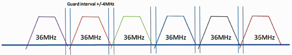
Figure 5. Wideband transponder
This yields two major improvements:
• Reduced CAPEX: only 1 modulator with a bandwidth at 500MHz is needed instead of 10 modulators at 36MHz
• Reduced OPEX: 1 satellite carrier of 500MHz instead of 10 carriers at 36MHz with their lost 10 percent bandwidth for the guard band
The schematic of Figure 4 demonstrates the OPEX savings: the “traditional” architecture contains several transponders with a maximum usable bandwidth of 36 MHz, plus a guard band inbetween each carrier.
In case multiple small bandwidth carriers need to be combined into one transponder, a global power back-off is required to avoid saturation of the satellite amplifier (multi-carrier effect). This means that any modification of one of these carriers requires a new calculation/adjustment for the satellite transponder.
In a wideband configuration (as per Annex M), only one channel is uplinked, as the individual small band-width carriers are combined at the modulator level. This means that guard intervals are no longer necessary and this bandwidth can also be used to transmit useful data. As shown in Figure 5, there is now only one channel, which:
• Increases the global data-rate since the power back-off can be reduced
• Improves the C/N margin, the C/N coverage of the spot beam
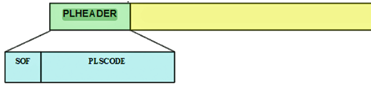
Figure 6. Traditional DVB-S2/S2X PLHEADER
Using wideband is the key for CAPEX and OPEX; but what about the resultant data-rate per service? Defining a service with 1 or 2 Gbits/s does not seem feasible. However, Annex M was introduced in the DVB-S2 / DVB-S2X standards to answer this challenge.
What Is Annex M?
First of all, the question is why Annex M? Regarding the EN 302 307 standard, Annex M specifies the implementation of DVB-S2 and DVB-S2X profiles suitable for operation in wideband mode, without requiring a full-speed decoding of the total carrier capacity, by suitably mapping the transmitted services in time-slices.
As introduced previously, the wideband configuration is a way to transmit over a single carrier a data-rate of some Gbits/s. On the reception side, of course, the user doesn’t want to demodulate so large an amount of data.
The user is only interested in one service available among the various other services. Annex M, at the service level, is an aggregation process for a number of services, following a rule which allows, on the reception side, the user to select easily one service out of several.
Annex M is a tool to give the opportunity for wideband operation to be available economically and arriving soon into the market, and also to give an answer to this question: How can one increase the data-rate today, by limiting the CAPEX and reducing the OPEX?
There is also another feature available in the DVB-S2/S2X standard which is used in another context: the multistream process. The idea is conceptually the same (reduction of CAPEX/OPEX) but the process is not done at the same level.
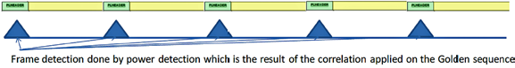
Figure 7. Frame Detection
As the plan is, at the first step of the demodulation, to select only the correct service, the process introduced by the Annex M is simple: add a label at the beginning of each DVB-S2/S2X frame at the physical layer level.
How does that work? Both these standards are based on the LDPC FEC process which works in frame mode. A frame can be sized either at 64800 bits or at 16200 bits.
To give the possibility to detect the beginning of each frame, at the modulator level, dedicated information must be added at the front of each frame: the PLHEADER or Physical Layer Header.
This PLHEADER is intended for receiver synchronization and physical layer signaling. PLHEADER starts with a sequence Start Of Frame (SOF) which allows, by correlation, the detection of the beginning of each frame as shown in Figure 6 on the next page.
The SOF + PLS CODE represent a “Golden Sequence” which exhibits some dedicated mathematical properties and which can be detected with a very low Signal to Noise Ratio. Thus, at the front of each DVB-S2/S2X frames, a PLHEADER is added containing the Golden Sequence, which allows easy detection of the start of the frame on the reception side, as illustrated in Figure 7.
Annex M also extends the PLHEADER by adding a Time Slice Number (TSN over 8bits), which identifies the service to be extracted by the receiver. When a wideband modulator is used with Annex M, the modulator generates this new PLHEADER, as shown in Figure 8.
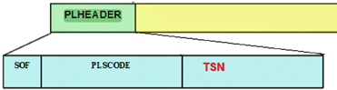
Figure 8. Wideband Annex M PLHEADER
Teamcast provides this kind of modulator (Tyger) where the input services can be either over ASI (traditional audio/video format over MPEG-TS) and/or over IP with the GSE encapsulation.
Due to the PLHEADER construction, the maximum number of services carried, at present is limited to eight. However, the idea of Annex M is to support service data-rates around the current data-rate capacity available on the DVB-S2 chipset, which is around 200 Mbps; with eight services, the global wideband data-rate would be nearly 1.6 Gbps. With an 8PSK constellation, this corresponds approximately to a satellite bandwidth of 500 MHz being required.
To summarize, wideband operation is possible if configured with Annex M. Annex M gives providers the possibility to introduce STBs onto the market with just a “small” step difference between a wideband STB and a current legacy STB. As shown in Figure 10, on the next page, the wideband process is introduced at the RF level, just after the tuner:
The complexity is at the tuner level, which must be wideband compliant up to 500 MHz. Note that this means a standalone wideband tuner would be not practical because of the close connection required between the tuner and the base band demodulator is mandatory.
What About The Receiver?
Can the receiver support a data-rate associated with a 500MHz bandwidth? Yes, such could be possible.
However, from an economics point of view, such a chipset would be too expensive—today, that is—but perhaps not over the next couple of years. That is why the DVB-S2/S2X standards with their Annex M is an advantageous solution which keeps the wideband demodulator chipset quite closely aligned to the current demodulator chipset used in the STB.
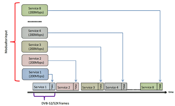
Figure 9. This represents the process that is applied to link a service with a TSN number:
At the lowest physical level, the chipset just selects the needed service and then demodulates only that service. This means a modification “just” at the receiver input tuner and keeping the rest of the receiver at the current performance and complexity level becomes possible.
On the reception side, one could make an analogy between the DVB-S2/S2X multistream process and the Annex M process. Basically, the idea is more or less the same: aggregation of services to reduce CAPEX and OPEX. However, there is a big difference between these two processes: the multistream receiver needs to demodulate all the full incoming data-rate streams and then select which service is needed, as shown in the schematic of Figure 11a.
In the Annex M receiver, the selection of the service is completed at a very low physical level, just after the tuner component, where the demodulator is looking for the beginning of the DVB-S2 or DVB-S2X frame. Each frame is identified by its Golden Sequence, with a different value for each service.
The Physical Layer Scrambling (PLS) sequence is different for Service 1 compared with Service 2. Therefore the service selection is made based on the PLS Header as shown in Figure 11b.
The big benefit is that the LDPC decoder needs only to handle the same data-rate as is already currently available on the S2/S2X chipset: roughly, 200 Mbps. At the system level, the DVB wideband-with-Annex-M technology could be deployed as shown in Figure 12.
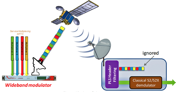
Figure 10. Time Slicing process.
What Is Currently Available On The Market?
Status Of The Ground Equipment
At this point in time, ground equipment and systems are typically focused on the traditional bandwidth of 36 MHz; however, TeamCast recently introduced a new modulator—Tyger4—which offers the capability to cover up to 500 MHz with different types of service—either traditional audio/video over ASI or Ethernet, or the new GSE-Lite protocol introduced in the DVB-S2X standard. With this product, TeamCast succeeds in proposing a new solution to reduce CAPEX and OPEX for the HTS satellite system integrators.
Status At The Projects’ Level
On the receive side, it is important that chipsets supporting the Annex M (Time slicing) solution are readily available to keep the cost low for the consumer. The company has shown in this article that the effort required to be ‘wideband compliant’ is not too high: in fact, it is limited to the tuner section of the receiver.
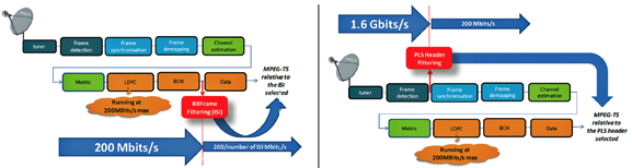
Figure 11a. multistream process; Figure 11b. (right) Annex M process
The rest of the demodulation/decoding process remains the same as in use today, as the same data-rate is preserved (+/- 200 Mbps). Currently, there are ongoing projects where wideband and Annex M are used; for example, the THD-SAT project in France, and the Spacebus 4000B2 platform in Bangladesh. Furthermore, ESA projects are already involving chipset manufacturers: this was reinforced during the last Toulouse Space Show, where TeamCast, with CNES and ST Micro Electronic, demonstrated a wideband transmission setup as shown in Figure 13.
The wideband modulator with the Annex M (time slicing) process together with HTS satellite technology is a major step for the satellite ecosystem toward delivering the extremely high data rates now required by the market, while meeting the time to market and cheap receiver demands of the consumer.
At present, the satellite transmission ground equipment is focused primarily on the traditional bandwidth of 36 MHz transponders. However, there are now wideband modulators coming onto the market that offer the capability to uplink using up to 500MHz wide channels.
TeamCast has introduced their new modulator, Tyger, which offers this capability, managing the Annex M implementation requirements for different types of services over a wideband signal up to 500 MHz.
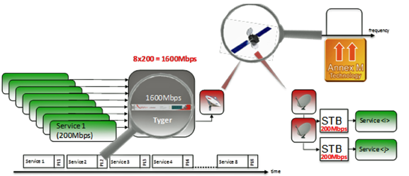
Figure 12. Wideband & Annex M on the system level
With this product, TeamCast is providing the ideal solution to reduce CAPEX and OPEX for the HTS satellite system integrators.
HTS wideband with DVB-S2X Annex M is ready for commercial deployment.
Resources
1NSR Source 2015
2DVB is a registered trademark of the DVB Project
3http://www.sia.org/wp-content/uploads/2016/06/SSIR16-Pdf-Copy-for-Website-Compressed.pdf
4http://www.teamcast.com/wp-content/uploads/2016/03/TYGER_Leaflet_MPD-151104E.pdf
TeamCast offers innovative technology offerings based on the firm’s solid expertise in Satellite and Terrestrial Digital TV transmission.
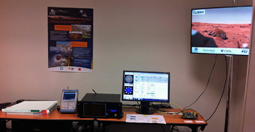
Figure 13. Wideband transmission setup
Created in 2003, and based at Rennes in France, TeamCast is involved in the development, definition and verification of numerous broadcasting standards, including DVB-S2X. TeamCast is an active member of the satellite Interference Reduction Group (iRG: www.satirg.org) and actively participates within the Carrier ID (DVB-CID) contribution in this group as well as in various exhibitions.
Today, major clients in the broadcasting Industry from 50 different countries invest in TeamCast technology and products. TeamCast has offices in Elmira, New York, and in Singapore to support the development of their North American and Asian business operations and to provide local sales and technical support services to customers across the globe.
www.teamcast.com