
Ka-band satellite systems are proliferating around the world, offering new bandwidth and business opportunities for commercializing the 20/30GHz frequency bands. However, as Earth stations expand beyond their traditional C- and Ku-band “comfort zone” into new Ka-band services, their designers and builders face challenges.
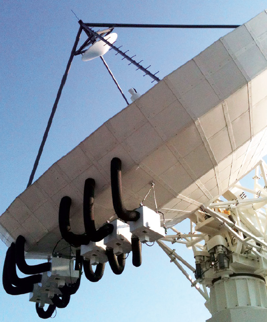
A Plenum hot-air de-icing system from Walton De-Ice that consists of an environmentally controlled, hot-air heating system that is mounted behind the large antenna.
Challenges with Ka-band links include much greater rain fade losses at Ka-band frequencies when compared to Ku-Band, as well as additional losses due to antenna wetting. Ka-band RF signals are far more sensitive to rain, ice and snow on the Earth station antenna. Ka-band Earth station design challenges include requirements for extreme reflector precision, optimized de-icing systems in cold climates, rain-shedding and rain diversion systems for antennas.
Ka-band uplink and downlink systems need all the help they can get to minimize link losses and to protect them against signal degradation and outages. Antenna de-icing and weather protection systems provide an important, practical and effective way to mitigate potential outages and signal loss and improve network performance and service quality.
Ka-Band Earth Station + Network Growth
The deployment of numerous Ka-band satellite systems around the world, (e.g., Spaceway, ViaSat, KA-Sat, WildBlue, Inmarsat Global Express, Eutelsat, DIRECTV, 03b, and so on) has driven the construction of accompanying ground infrastructures of fixed Ka-band Earth stations, VSAT hubs, and the wide use of Ka-band remote terminals. Earth station manufacturers and integrators, such as ASC Signal, General Dynamics SATCOM Technology (formerly VertexRSI) and ViaSat, have enjoyed significant demand growth for Ka-band products. They have sold or installed several hundred new large Earth station antenna systems in recent years to support these new Ka-band commercial systems. These hub antennas now serve millions of DTH subscribers, broadband terminals, important military, government, and business networks.
Because many of these large antennas have been installed in locales where snow and ice is of concern, demand has also grown for antenna de-icing sub-systems from companies such as Walton De-Ice, (www.de-ice.com) which leads the market with more than 125 Ka-band antenna de-icing systems delivered across the globe. The San Bernardino, California-based Walton De-Ice company has been in the de-icing business for satellite Earth station for more than 35 years.
Ka-band Challenges
Demand for Ka-band systems has highlighted many “new” technical challenges from an Earth station and network design standpoint, as compared to traditional (C-, Ku- and MSS band) requirements. Suppliers indicate these challenges include:

• Antenna surface and tracking accuracy: Ka-band Earth stations require high-accuracy tracking and a high accuracy reflector due to the narrower Ka-band beam width, compared to Ku-Band. The narrow beam width requires more precise antenna surface regularity, and wind loss compensation.
• Atmosphere and Rain: Atmospheric phenomena, rain, snow and ice absorb radio frequency signals at Ka-band so that a Ka-band signal suffers more degradation than a Ku-band signal. For example, rain attenuation at 31 GHz (Ka-band) is almost three times that of 12 GHz (Ku-Band). Since rain fades can be very large, at Ka-band, uplink power control and stability become more challenging.
• Antenna Wetting / Wet Antenna Effect: A perhaps less well-known item is that in Ka-band communication systems an additional signal margin should be included to account for the wetness of the antenna system . (Dry snow has a minimal effect on Ka-band propagation.) Water on the main reflector, and even more critically, the feed aperture, is a major source of loss at 20 and 30 GHz.2 The amount of water or snow on Earth station antennas (ESAs) can cause additional signal degradation above and beyond the expected propagation attenuation due to rain alone. Rain on a reflector can create a distorted reflector surface that reduces the antenna gain by several dB in the worst case. Water on the feed aperture distorts the electric field’s distribution of the feed therefore creating a high perturbation on the feed standing wave ratio (SWR). One laboratory test measured and calculated the antenna attenuation due to surface wetting can reach 10 dB at Ka-band. The antenna attenuation during rain at any instant of time relates to the amount of water accumulated on the antenna surfaces at that instant. It is, however, largely independent of the instantaneous rain rate.
Boosting Reliability
Uplink and downlink signal margins are precious resources at Ka-band, adding up to a simple point: Ka-band uplinks and downlink systems need to minimize link loss and gain outage protection.1
In cold climates, measures must be taken to remove wet snow and ice accumulation from the surfaces of antennas and feeds. For rainy climates, water-shedding and runoff performance requirements are beginning to appear in Ka-band system specifications. Technology providers, such as Walton De-Ice, have introduced new innovations such as the Rain Quake and Ice Quake systems that mitigate Ka-band antenna wetting.
Ka-band Uplink / Large Antennas
Solutions to de-ice for large, uplink antennas 5 to 32 meters in size include:
• Plenum systems, which recirculate hot air into an enclosure behind the antenna reflector
• Pad Heating and Heat Tape, which use heated elements attached to the rear of the reflector and do not affect the back structure
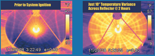
This image depicts how uniform antenna surface heating minimizes distortion losses. In this example, infrared photo measurements of heat across a large antenna reveals the temperature variation before, and after, the Walton De-Ice system has been activated. Image courtesy of Walton De-Ice
Depending on the application, manufacturers may offer electric-powered, and/or gas (liquid propane, and/or natural gas) heaters. If not well designed, these units can produce high antenna gain losses (up to 6dB). Non-uniform heat applied to the antenna structure can cause defocussing and reflector degradation, as mentioned previously.
Walton De-Ice has refined its unique, field-proven, plenum, hot-air de-Icing system, with a unique hot-air enclosure system that mounts behind the antenna. The Walton De-Ice plenum solution offers several advantages over electric pad or heat tap anti-ice systems—the circulation of hot air provides uniform surface heating of antennas resulting in a totally effective elimination of ice.
Automatic temperature sensing and integrated control of the Walton De-Ice Plenum ensures that sufficient heat is uniformly applied to the reflector surface to minimize the thermal effects on antenna gain. The design itself minimizes thermal expansion of an antenna structure. Temperature distribution is controlled with the use of circulation fans and heat distribution systems within the plenum. A Temperature Balance Controller is integrated into the standard automatic monitor and control units to measure, control, and optimize surface heat distribution in real-time.
Results show transmit and receive gain degradations at Ka-band reduced, for example, to the 0.6 to 0.75dB range for 9.2m-13.2m Ka-band antennas. That is a dramatic performance improvement when compared to the previously mentioned 6dB figure.
Boosting Energy Efficiency
One of the newer developments has been the introduction of more energy-efficient heating systems and options to help reduce Earth station operating expenses and to support corporate Green initiatives. For example, Walton De-Ice has added a new, higher level of CE (European Union)–certification to the gas heating units that are now available worldwide.
“Our new CE-certified gas heaters combine with the Walton De-Ice Plenum system to offer unparalleled performance and reliability and deliver the most rapid and cost-effective solution for preventing snow and ice buildup 24x7 at the lowest operational cost for an Earth station antenna,” said David Walton of Walton De-Ice. “The new Gas Heater is easy to upgrade on existing antennas by using the same wiring and mounting configuration as Walton’s original heaters,” he added.
Reflector Distortion Losses
Antennas have reflector panels that are mounted onto truss supports that are then tied together. Anti-icing solutions that only heat the individual reflector panels cause distortion losses by creating temperature differentials between the reflector panels and the truss supports. Metals expand at different rates when heated. Antenna panel thickness and size varies. This size difference can contribute to the uneven heating of a reflector’s metal panels with pad-based anti-icing solutions, as they tend to leave a checkerboard footprint that creates cold and warms strips on the reflector surface. In contrast, Walton Plenum hot air de-icing encloses the entire back structure and uniformly distributes the heat.

Solutions
Walton De Ice’s systems are controlled by a Temperature Balance Controller (TBC) device that monitors four separate areas within the plenum and also incorporates a thermostat in which, once the reflector surface reaches a certain temperature (that occurs much faster than with a heat pad anti-ice system), heating is then activated only long enough to re-heat the space again.
A pad-based anti-icing system must maintain heating, even if it has a temperature threshold that turns the system on automatically when a cold weather threshold is present. This solution consumes far more energy dollars than, for example, a gas-heated, Walton Plenum solution, which detects the presence of moisture and temperature, and responds by rapidly and uniformly heating the antenna, thereby conserving power.
For antenna subreflector and feed de-icing, Walton De-Icing systems re-use the heated air from the Plenum, which is ducted to the feed horn and subreflector, using a blower. The same systems also perform rain diversion to clear the feed horn window of moisture, which can severely degrade Ka-band signals.
When It Rains On Ka-Band, It Pours
As previously noted, rain fade is a significant challenge for Ka-band systems. Signal attenuation at Ka-band during heavy rainfall can be as much as four or five times that of a C- or Ku-Band antenna.
Antenna wetting, a function of rain in density, antenna type, frequency, and elevation angle, can contribute to a 2.7-3.9dB of link losses at the 20/30GHz Ka-band range. Rain-caused signal depolarization can add fade levels of more than 10dB.
Fortunately, there are solutions such as the one introduced by Walton De-Ice, which has developed an innovative new way to mitigate rain and antenna wetting effects. The Walton De-Ice Rain Quake system can significantly reduce the impact of rain fade on Ka-Band antennas and protect their antenna G/T performance. For warm and rainy climates, the system prevents rainwater from sheeting on an antenna surface and works on antennas that range in size from 0.6 meter VSATs to large antennas up to 6 meters in diameter. The system also prevents rain fade caused by sheeting on the antenna reflective surface for Ku-band antennas.
The Rain Quake cover stretches over an antenna, keeping rain off with a water-shedding, architectural fabric material that is virtually invisible to RF. By vibrating the fabric, rain is rapidly shed off the antenna.
“Field testing has shown that during heavy rain conditions, Walton Rain Quake systems can reduce data loss by more than 20X when compared to Ka-band antennas without protection,” said Walton. Tests show that the Rain Quake System helps to minimize bit error rates while antenna noise temperature increases, thereby improving Ka-band system link margins during a rainstorm.
Innovations
For cold climates, the Rain Quake is referred to as an Ice Quake. The Ice Quake version of the product prevents snow and ice buildup on antennas from 0.6 to 6.3 meters in diameter.
The Walton antenna cover, called a Snow Shield, is made from extremely durable, architecturally coated, fabric material, again, virtually invisible to RF. The Snow Shield stretches over a satellite antenna and can be used as a Passive solution without a heater or as a heated solution. Walton De-Ice has patented the combination system of the antenna cover plus the active heating component. As the sun moves from east to west, an antenna reflector is susceptible to hot and cold spots that also result in reflector distortion losses. Earth station owners have discovered an additional benefit using the Snow Shield Cover—the product also acts as a Solar Cover, helping to evenly distribute warmth from the sun to minimize distortion losses.
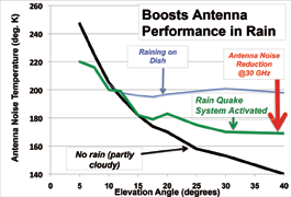
Reduction in Ka-band Antenna Noise Temperature with Antenna Cover Image courtesy of Walton De-Ice.
According to Walton De-Ice, the advantages of their modular Snow Shield / Solar Cover / Rain Quake / Ice Quake solution is that the antenna cover can remain in place on an antenna year-round. Other covers on the market typically need to be removed during summer months due to UV rays that cause the material to break down and absorb water, dirt and grime. A disadvantage with these kinds of covers is that the antenna user must replace such covers every few years. This translates to additional costs in manpower, downtime as well as the new covers cost.
The Ice Quake enhances the performance of the Snow Shield antenna cover by vibrating the cover fabric, shaking off snow and ice that degrade signals. According to David Walton, “The Ice Quake system offers huge savings—up to 100 times—on an electric bill versus competing anti-ice systems. An automatic moisture and temperature monitoring and control unit ensures 24/7 operation. By eliminating the need for a high power conduit, trenching, and electrical switch gear in a facility, the method also saves costs compared to the installation of conventional electric heating systems.”
In addition to the energy-saving vibrating fabric, for the highest level of de-icing, a gas or electric heater may still be added as a post-install to the passive Snow Shield or Rain Shield. This is completed without removing the cover and avoiding antenna downtime
Ka-band Earth station design challenges are being met with tightened design and production tolerances, more advanced antennas, power amplifiers, and frequency converters, as well as improvements in weather protection systems. Healthy Ka-band market demand is pushing manufacturers, such as Walton De-Ice, to continue to innovate and expand their product line to provide customers with more solutions to ensure their VSAT and large satellite Earth station antennas are fully operational during the harshest environmental conditions.
Ka-band network operators and designers can better protect their critical satellite networks from signal loss and degradation due to ice, snow, rain, and sun by adding optimized de-icing and rain-shedding sub systems to their existing and planned earth station antennas. The correct Ka-band Earth station antenna de-icing, or rain cover sub-system, can yield excellent “bang for the buck,” helping operators maximize Ka-band signal, service quality and reliability in the face of Ka-band link challenges.
For additional Walton De-Ice information, please visit http://www.de-ice.com/kaband.html
References

1http://ascsignal.com/files/news/2014/ASCSignalSecuresRecordNumber-Ka-bandContracts.pdf and http://www.gdsatcom.com/email/GDST_Oct2012_Nocedal.pdf
2“Take advantage of smaller beam widths and higher frequencies in antenna designs,” Rory Eddings, Joe Tolleson, Dan Vorderbrueggen, Andrew Corp. http://www.eetimes.com/document.asp?doc_id=1276255&
About the author
Daniel Freyer is the Principal of AdWavez Marketing (http://www.AdWavez.com), an agency specifically serving the satellite industry.