
This AsiaSat article presents some concepts on the VHTS gateway rollout scheme. The practical implementation of these concepts may be tied to specific satellite payload designs and the available space-ground segments control management system features.
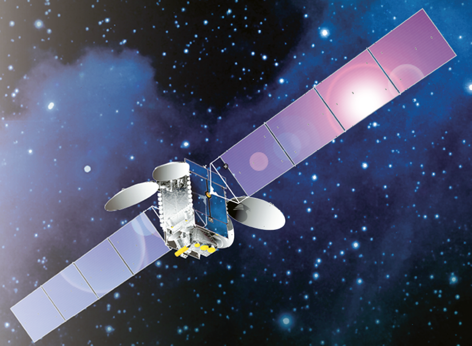
Artistic impression of AsiaSat’s satellite on orbit.
With the advanced technology development in the multi-beam High Throughput Satellite (HTS) industry, the achievable capacity of a single HTS can be further enhanced to more than 500 Gbps and become a Very High Throughput Satellite (VHTS) system.
To realize such enhancement, the ground gateway system deployment must be carefully designed and implemented. In principle, the total amount of usable capacity of a VHTS is directly proportional to the total number of active gateways in the whole network.
When VHTS operators consider the actual business deployment, several challenges must be evaluated and addressed as below to ensure business sustainability and a timely profit:
• User capacity demand over time and region
• Strategy of New network implementation versus Existing network migration and expansion
• Scalability for additional gateways
• Flexibility to increase system throughput
• Investment allocations
• Risk mitigations
• Service level opportunities (i.e. coverage area, data rate supported and gateway redundancy)
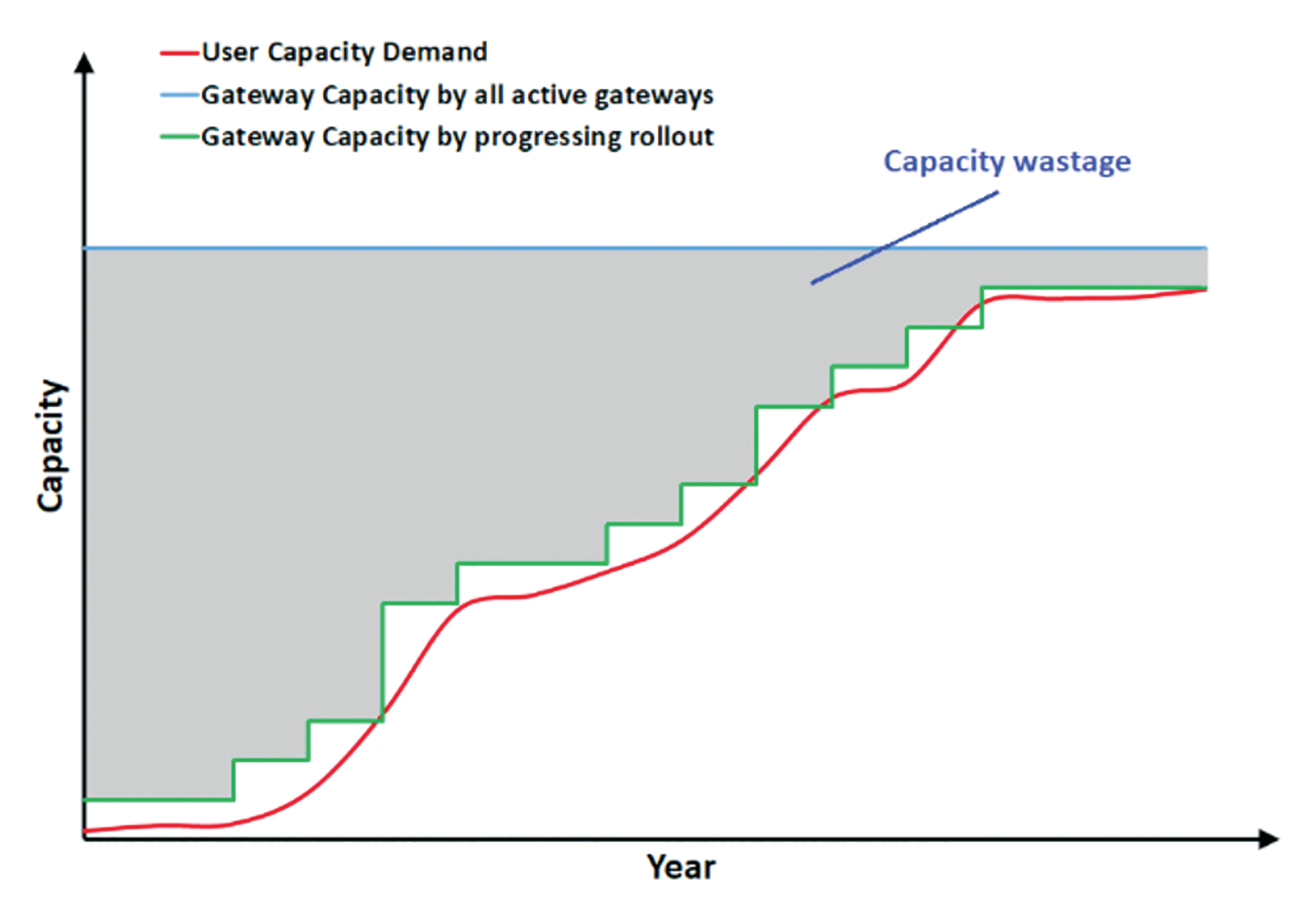
Figure 1. Illustration of capacity demand variation over a satellite mission life.
Figure 1 illustrates the scenario of deploying all active gateways from the beginning and deploying the gateways progressively to minimize the idle capacity. In this example, there is a huge amount of capacity wastage indicated by the shaded area over the years, if user demand ramp-ups are not properly considered. This is not a desirable situation in terms of investment, or in return and risks.
To address the aforementioned VHTS ground network deployment issues, this article presents some concepts on the VHTS gateway rollout scheme. The practical implementation of these concepts may be tied to specific satellite payload designs and the available space-ground segments control management system features.
Gateway Network Rollout Methodologies
Frequency Domain Method
The frequency domain rollout can be demonstrated by the deployment of a 750 Gbps VHTS system. In this example, it is assumed the average spectral efficiency (SE) is 2 bps/Hz and at least 4 GHz gateway forward bandwidth as shown in Figure 2. The forward (FWD) to return (RTN) traffic ratio is assumed to be 2:1. Conventionally, the operator of this VHTS has to make available at least 64 gateways before the satellite launch, which would be a huge CAPEX investment.
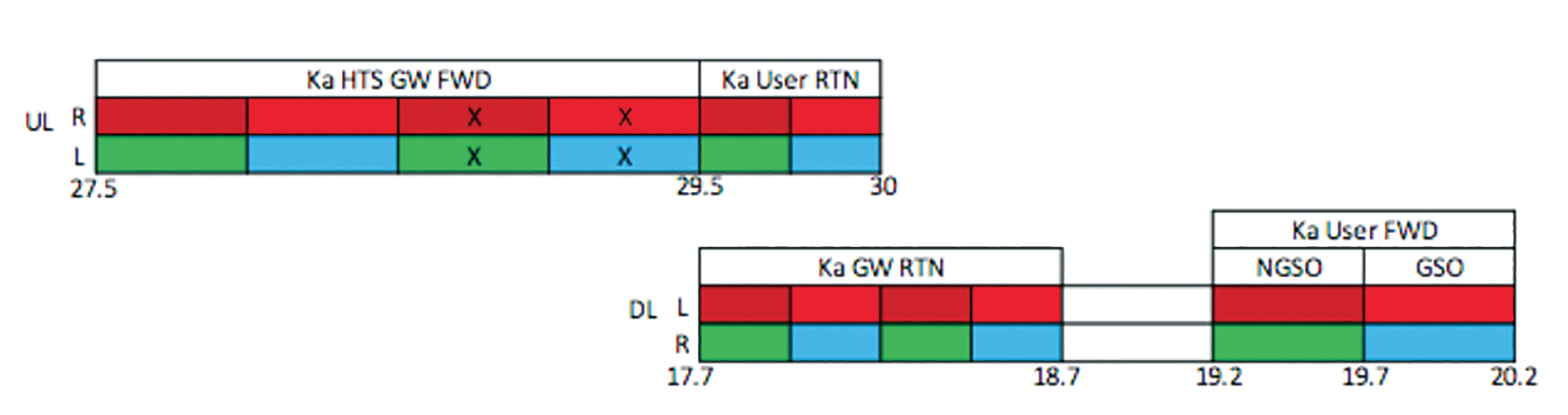
Figure 2. Frequency plan of a typical Ka- HTS.
In order to minimize the initial investment of ground facility, progressive gateway rollout in frequency domain can be considered with properly designed satellite payload system. For instance, the 500 MHz user beam spectrum can be sub-divided into 4 by 125 MHz channels in each beam as shown in Figure 3.
These sub-channels can be rolled-out sequentially in four different phases. In the initial phase (phase 1), only 16 gateways stations are needed to provide full coverage, which is just one fourth of the total gateway facility CAPEX. In the followed three phases, the number of gateways will be gradually added. Table 1 has illustrated this rollout plan for the 750 Gbps VHTS system.
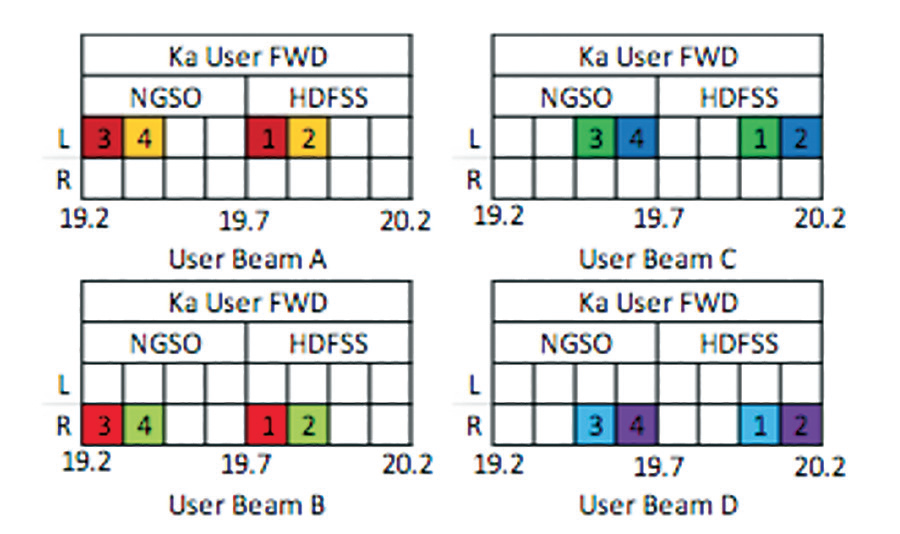
Figure 3. User beam frequency segmentation. The numbers in the cells indicate the gateway rollout phases.
The detailed frequency plans for each gateway rollout phase is illustrated in Figure 4 on the next page. In phase 1, a total of 16 gateways are deployed to serve all 512 user beams. Each gateway serves eight sets of 4-color reused user beams. The capital letter in Figure 4 indicates the frequency allocation of each set of 4-color reuse beams. Each user beam will have 125 MHz usable bandwidth which can provide one fourth of the total throughput capacity. The numbers in the user beam cells indicate the rollout phases. In the last phase, i.e. phase 4, each user beam will have a total of 500 MHz bandwidth fed by a total of 64 gateways.
This frequency domain rollout method can be realized by either an analog or a digital satellite payload system. In the analog payload implementation, filter banks or multiplexer banks can be used. In the digital payload implementation, an on-board digital channelizing processor can be used. Figure 5 illustrates the feasible satellite payload realizations.
It has been shown that frequency segmentation provides a method of minimizing the initial investment of the gateway facility. However, due to the limited Ka- gateway uplink frequency spectrum (2 GHz each on the two orthogonal polarizations as shown in Figure 2), a significant number of Ka- band gateways have to be built eventually to support the high throughput target. To further minimize the total number of gateways, we can also deploy the VHTS by progressively migrating the gateway links to the even higher frequency bands such as Q (40 GHz) and V (50 GHz) bands. Thus, another 3-phase rollout example of a 750 Gbps VHTS is introduced below.
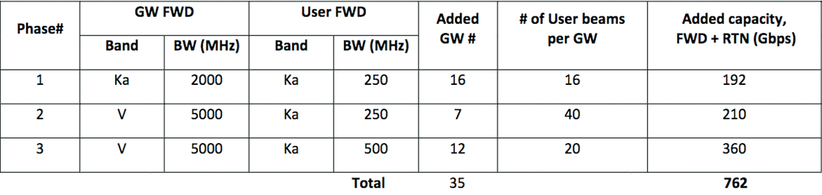
Table 2. Q/V band gateway rollout implementation of a 750 Gbps VHT
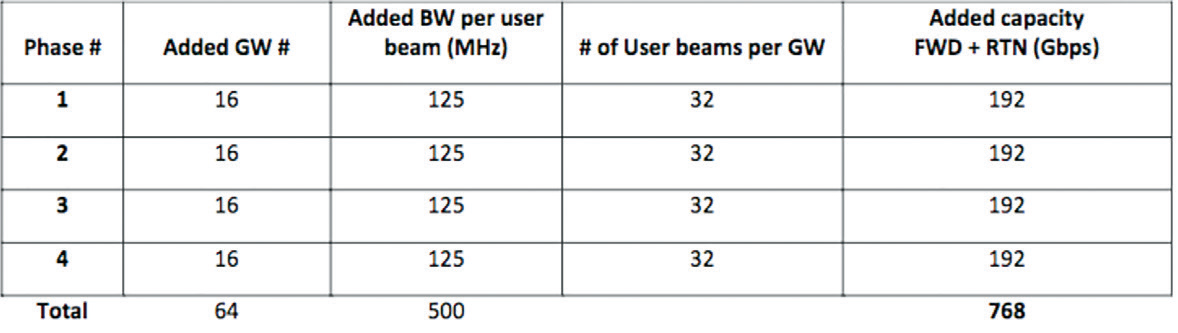
Table 1. Frequency-domain gateway rollout plan for a 750Gbps VHTS system
As shown in Table 2: At phase 1, only Ka- band spectrum is used for gateway links, which enables a full coverage of 256 user beams with a throughput of 192 Gbps. At phase 2, V band is used for gateway uplinks, providing an additional capacity of 210 Gbps.
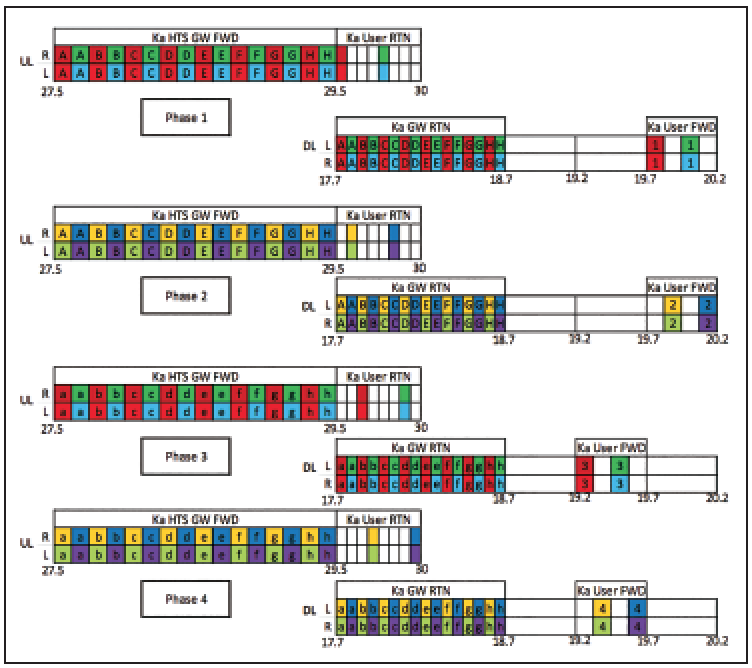
Figure 4. Frequency plans for the rollout of a 750 Gbps VHTS
At phase 3, gateway downlinks are switched to Q-band, which frees up to 2 GHz in Ka-band that can be used by the user beams, and thus another 360 Gbps can be added by the 12 new Q / V band gateways. The phase 3 user beam forward spectrum is illustrated in Figure 6 below. In this demonstration, the targeted 750 Gbps throughput is achieved by only 35 gateways, which is 45 percent less than that in the first example, where only Ka-band is used for the gateway and user links.
This progressive rollout method can be further extended with user beams using V and Q-bands, with the gateway links moved to optical spectrum. A multi-band user beam antenna system can also be adopted in the VHTS. With proper optimization on the feeds and the reflectors, the spot beams of different bands can be seamlessly overlaid on the same geographical area with similar or different beam widths [1]. By using this method, as shown in Figure 7, the VHTS operator can firstly rollout the Ku user spot beam capacity and then 5 to 10 years later progressively move on to Ka- and Q- band user beams in accordance with the traffic needs and the maturity of the ground user terminals. Correspondingly, the operators and users can deploy their gateways and terminal facilities on a step-by-step and frequency band-by-band basis to save unnecessary CAPEX costs until the future demand arrives.
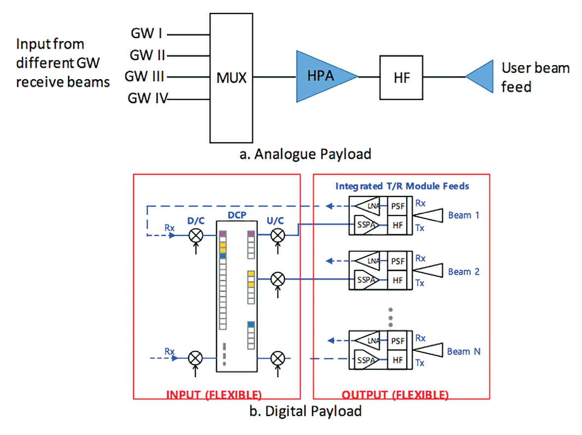
Figure 5. Example of analog and digital satellite payload design.
Spatial Domain Method
To adapt the flexibility and scalability for adding gateways in the network, the implementation of beamwidth control can be considered. For example, Beamforming is a well-known technology by integrating different elements in an antenna phased array in such a way that forming signals with constructive or destructive interference to control both the antenna gain and pattern. This technology is considered by the industry an essential element for next generation HTS and is commonly as displayed on the product roadmap. When it is applied to a HTS system, the beam size of each spot beam can be adjusted selectively. The typical spot beam antenna gain patterns with different beamwidths can be referred to Figure 8.
are switched to Q-band, which frees up to 2 GHz in Ka-band that can be used by the user beams, and thus another 360 Gbps can be added by the 12 new Q / V band gateways. The phase 3 user beam forward spectrum is illustrated in Figure 6 below. In this demonstration, the targeted 750 Gbps throughput is achieved by only 35 gateways, which is 45 percent less than that in the first example, where only Ka-band is used for the gateway and user links.
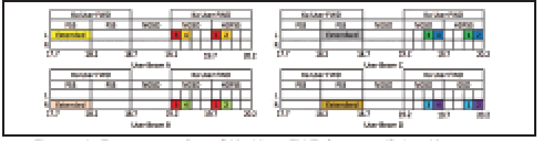
Figure 6. Frequency plan of Ka- User FWD beam utilizing Ka- gateway downlink spectrum.
Smaller beamwidth can provide more focused beam and hence higher gain. Within the same desired coverage area, more number of beams can be implemented by reducing the beam size in the beam layout. As a result, the aggregate throughput can be increased accordingly. Using this concept can help the gateway rollout in multiple stages when the capacity demand ramps up. For example, at the beginning of life, the beamforming adjusts the beams to a relatively larger size when the demand is minimum. When the demand starts to grow, more active gateways can be set up to serve additional capacity. These additional gateways can be located and accommodated through a smaller beamwidth with the beamforming adjustment. As a result, the ground network capability can be enhanced dynamically until reaching the maximum level in the design.
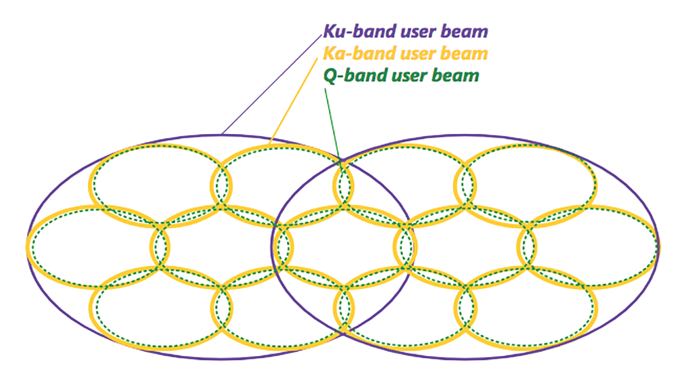
Figure 7. Example of VHTS progress rollout in a band-by-band basis
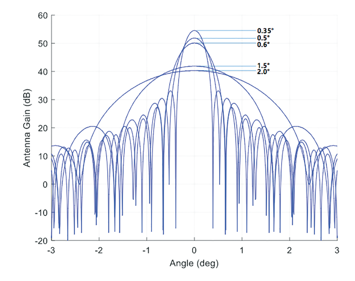
Figure 8. Antenna gain and pattern vs different antenna beamwidth
Time Domain Method
The HTS capacity rollout can also be efficiently realized by a time domain method thanks to the on-board digital channelizing processor (DCP). A DCP digitizes and channelizes the incoming signal and processes it in digital domain. The DCP multi-cast function is to be exploited in the rollout campaign.
The initial state of the HTS rollout is shown in Figure 12 (a), where one single TDM (Time- Division Multiplexing) carrier is uplinked from the only gateway station. This carrier is then duplicated and multi-cast by the DCP to all user downlink spot beams in different RF frequencies and polarizations (i.e. multi-color reuses). The user terminals (UTs) in different beams will lock the carrier and extract only the designated data stream. The time domain data stream lengths can vary for different beams to meet the different levels of demands.
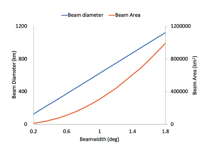
Figure 9. Spot Beam diameter and area vs beamwidth, referenced to the beams close to Nadir
In the expansion phase, two schemes can be implemented. The first one is to expand the gateway spectrum. As is illustrated in Figure 12 (b), four carriers are uplinked from the gateway and then multi-cast to all user beams. Consequently, more TDM data streams are added for the user beams and the total throughput of the system is quadrupled. To generalize the implementation of this scheme, the gateway spectrum may not be limited to conventional Ku and Ka- bands, but higher frequency bands like Q and V bands and even optical links can be exploited. The merit of this scheme is that only one or few gateways are needed to feed the whole HTS system.
The second scheme is to expand the number of gateways. With sufficiently spatial isolations, the additional gateways can fully reuse the whole gateway spectrum, adding more TDM data stream capacity to increase the HTS system throughput. This scheme is illustrated in Figure 12 (c), where eight carriers are uplinked by two gateways, where the capacity would be eight times of the initial state. With the increased number of gateways, the merit of this scheme is the relaxed requirement on each individual gateway (RF and baseband equipment) which can reduce the total cost of the system.
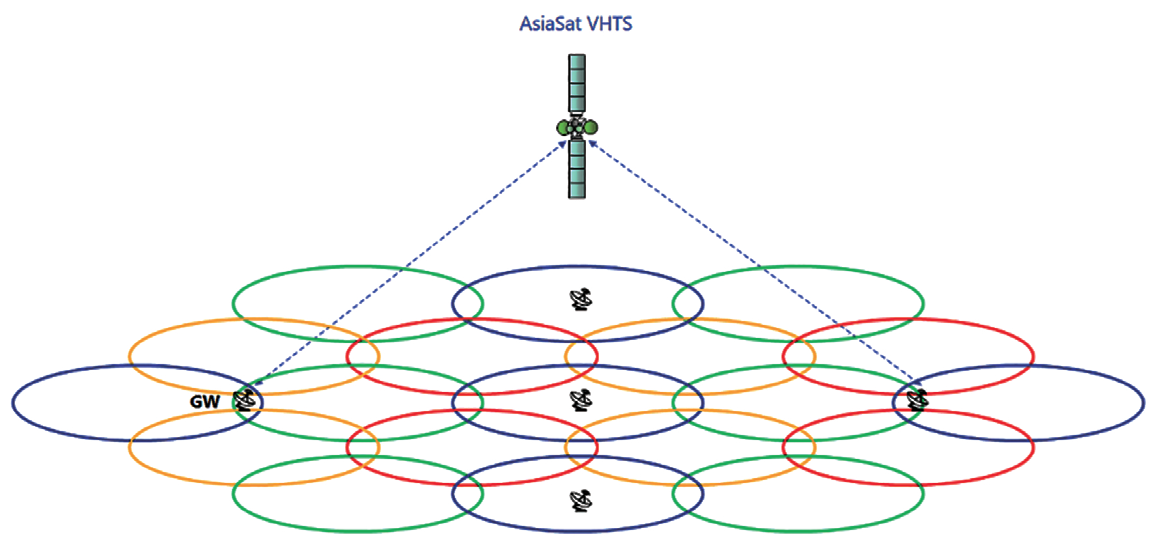
Figure 10. Beam layout with larger beamwidth; smaller number of beams and active gateways.
The time-domain rollout scheme must be supported and controlled by the ground network management system, so that the traffic between gateways and user beams can be maintained in the expansion phase.
Beam-Hopping Method
The beam-hopping method, which is a frequency, time and spatial domains combined reuse method, can also be used in HTS deployment and gateway rollout. The beam hopping HTS communication payload can realize the required flexibility with full analog RF components, but the cost is a more complicated ground-satellite system.
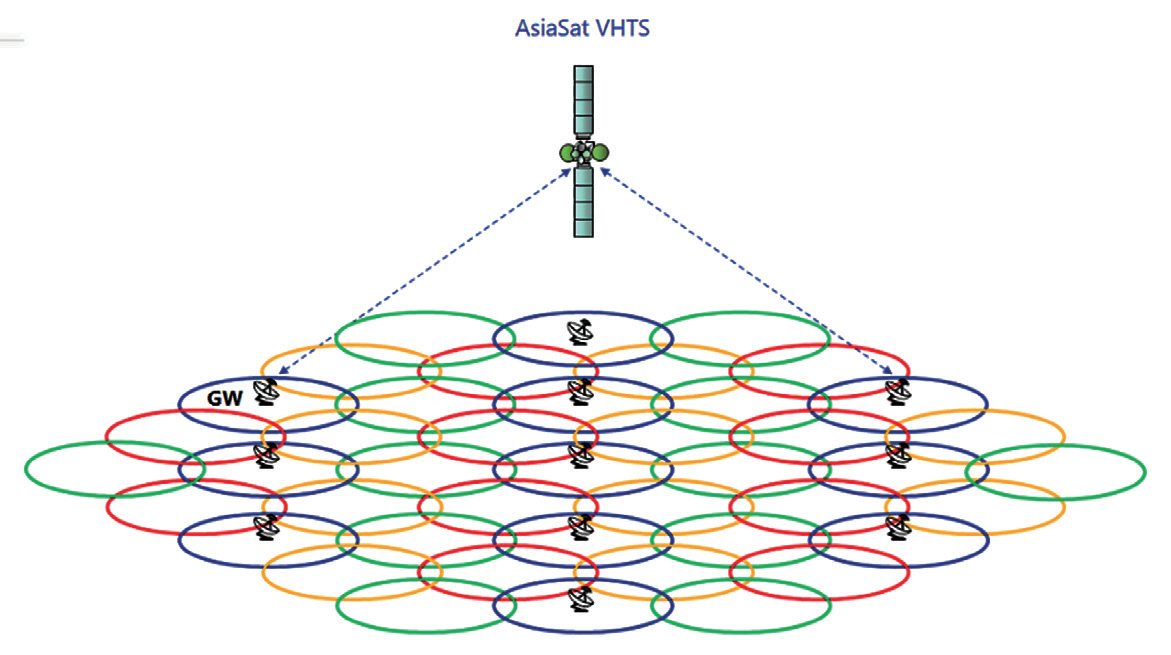
Figure 11. Beam layout with smaller beamwidth; larger number of beams with additional active gateways.
The beam-hopping HTS gateway rollout scheme is illustrated in Figure 13. In the initial state, the gateway uplinks one single carrier to the satellite payload. However, unlike the TDM HTS system, the carrier will not be received by all beams at the same time. Instead, it will be switched (or “hopped”) in between user beams in a predefined sequence and duty cycles. By controlling the dwelling time lengths and intervals, the throughput demand from each beam can be correspondingly met. Full spectrum can be used in each user beam to increase the capacity.
To ensure the user downlinks keep pace with the gateway uplinks, the actuation of the on-board output switches (e.g., sw1 in Figure 13 (a)) must be synchronized with the gateway transmission as well as the user beam receiving time patterns. This implies that a new and complex payload-gateway-user terminal control and management system must be established with stringent timing and synchronization requirement. The existing DVB-S2X standard has an optional feature of super-frame structure that supports the implementation of HTS beam hopping [2], which can be adopted by the HTS equipment manufacturers as well as the HTS operators.
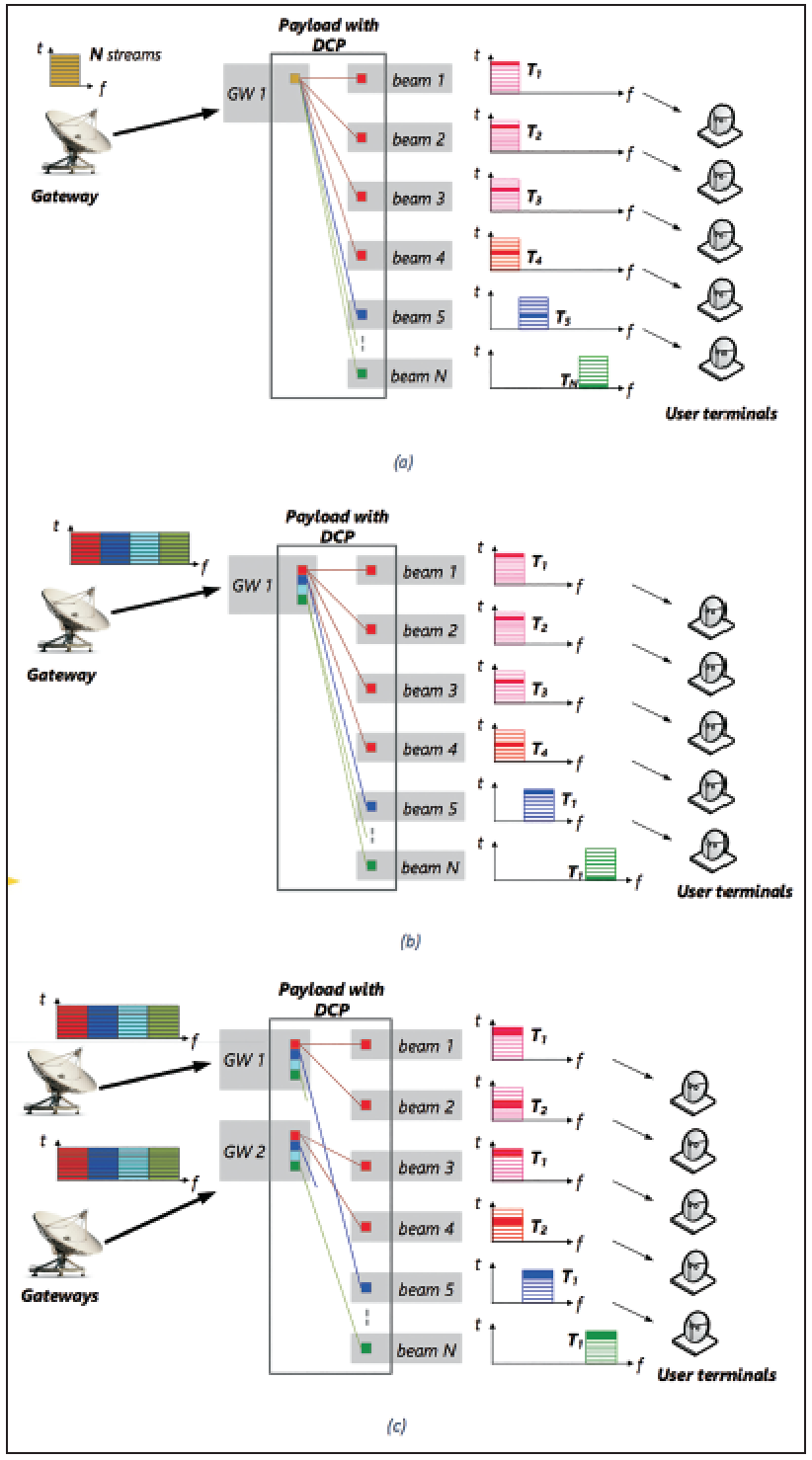
Figure 12 Time-domain HTS gateway rollout scheme, (a) the initial state, and capacity expansion by expanding (b) Gateway spectrum (frequency domain), and (c) number of gateways (spatial domain). The vertical and horizontal axes in the above figures are the time (t) and the frequency (f), respectively
To expand the capacity of the beam-hopping HTS system, more than one gateway can be employed, as shown in Figure 13 (b), where each gateway serves a portion of all user beams. To reduce the inter-beam interference, the beam hopping sequences for each gateway can be optimized so that no adjacent beams are dwelled at the same time. The conventional frequency/polarization color reuse scheme can also be adopted for different user beams so that each gateway can dwell more than one user beam at the same time and reduce the time interval between two consecutive dwellings on the same beam.
Conclusion
Gateway rollout planning is critical to enhance the efficiency of HTS/VHTS business economics as well as provide a high quality user experience. This article has discussed several ideas of gateway rollout in the aspects of frequency, time and spatial domain to adapt different scenarios. AsiaSat is excited by the great potential of HTS development in the market, and we are committed to delivering optimal solutions for the different needs of our customers. By working with our customers, partners and suppliers, we believe we can reach further by serving next generation HTS services to the Asia Pacific region.
www.asiasat.com
References
[1] AsiaSat, “Dual-band communication satellite system and method”. Submitted to USPTO at 2016.
[2] ETSI, “Digital Video Broadcasting (DVB) second generation framing structure channel coding and modulation systems for Broadcasting Interactive Services News Gathering and other broadband satellite applications Part 2: S2-Extensions (DVB-S2X)”, Annex E.1, p100, Draft ETSI EN 302 307-2, v1.1.1, Oct, 2014.
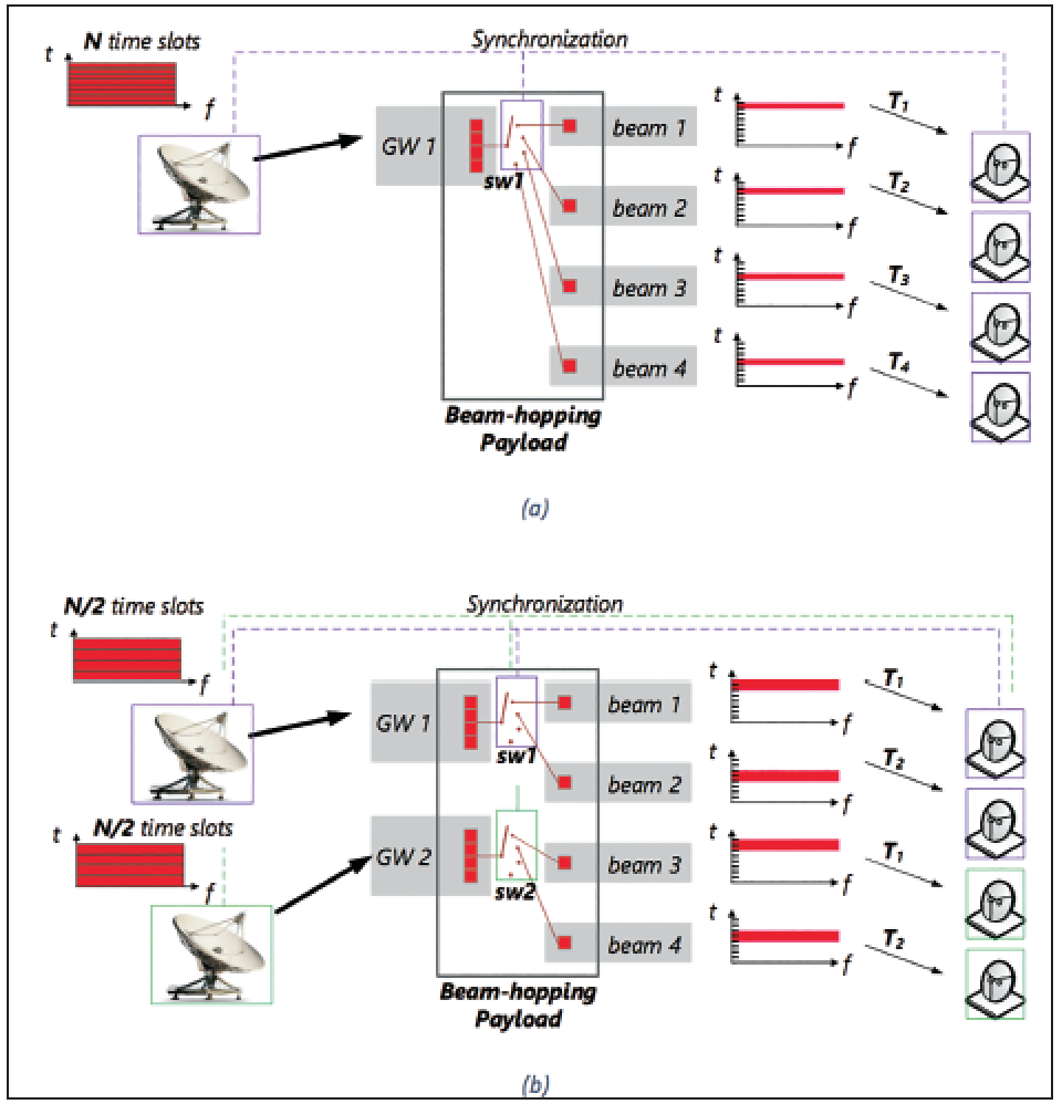
Figure 13 Beam-hopping HTS gateway rollout scheme, (a) the initial state, and (b) capacity expansion with more than one gateways.