
AvL Technologies is widely recognized as an industry leader in parabolic antenna technology and, in particular, rugged and robust transportable systems with mechanical positioning that is built to last and insanely reliable.
With more than 25,000 antenna systems deployed worldwide, AvL’s products are found in nearly every terrestrial environment and have enabled satellite communications to reach millions of people.
Over the last 10 years, customers have been requesting antennas that are smaller, lighter, more powerful and more versatile, including antennas that operate in multiple bands and antennas that communicate with satellites in GEO, MEO and LEO orbits. While this has been doable for some time with parabolic Earth terminals, it’s challenging and incredibly complex to do so with flat panel antennas. But new technologies emerge quickly, and soon — perhaps quite soon — flat panel antennas will be operating in significant numbers and for many different applications.
The most significant driver of demand for flat panel antennas is form factor, form factor, form factor. Flat panel antennas are small, compact, transportable, require little power and most offer high throughput. Newer, now emerging technologies also will enable spectral efficiency and the ability to move from beam to beam for LEO and MEO operation as well as the ability to track two satellites simultaneously. Additionally, advances in software defined radio and radiation pattern reconfiguration will enable communications to multiple satellites with multiple bands and orbits — all with one terminal.

Another driver is few or no moving parts. Though antennas with mechanical steering are sometimes disparaged because of the potential for mechanical issues, many mechanically-steered antennas have operated for decades without a problem. Mechanical steering can be a benefit to parabolic and flat panel antennas as it enables a much broader range of elevation, and thus can enable operations in more far-reaching locations and for a broader range of applications. That said, electronically steered flat panel antennas are in demand and when configured with multiple collaborative panels, can offer near or full hemispherical coverage without any moving parts.
Communications-On-The Move, or COTM, is yet another important driver of flat panel antenna technology. The desire to continuously communicate from a moving aircraft, ship or vehicle has fueled significant investment in technologies that adapt to an environment instead of being limited by it.
Flat panel antennas use several different technologies — some emerged in the 1970s and 1980s and some are emerging today. Most flat panel satellite communications antennas are waveguide based with horn or slot array antennas with mechanical steering, printed circuit board (PCB) antennas with mechanical steering, or active electronically steered arrays.
Waveguide Based Array Antennas
A waveguide based array is one of the most conventional implementations of a flat panel antenna. Waveguide is used for the feed network, and also forms the basis of the radiating element. Many times a horn is used as the individual antenna element. A horn antenna is exactly what you think it is — an antenna in the shape of a horn that directs energy through the horn. Thus a horn array antenna is an antenna comprised of many horns with energy being directed to and from a feed network to the back side of the horns. A slot can be used in a similar manner. Because energy projected through these radiating elements cannot easily be redirected in multiple directions, such waveguide based array antennas must have mechanical steering. In some cases, depending on the bandwidth of the element, and the required element spacing, transmit and receive arrays can be integrated or exist as separate entities.
Waveguide based array antennas are often used for high frequency applications including satellite communications and radar. This is due to the low loss nature of waveguide as a transmission line, particularly when compared to PCB based antennas and respective feed networks.
Limitations of such arrays typically include a complex and expensive manufacturing process that ultimately produces a thick overall structure as compared to PCB based alternatives. Bandwidth limitations of the radiating element may also be a consideration, and though slots are typically more compact than horns, they tend to be of lower bandwidth.
Printed Circuit Board Antennas with Mechanical Steering
Printed circuit board (PCB) antenna arrays are very popular in published technical literature whereby an array is created using a radiating element such as a square or round patch antenna.
The feed network may be composed of either a PCB based structure or a waveguide subsystem. PCB antennas can be easily modified with various shapes and sizes to optimize bandwidth or discrete patterns with exceptional diversity due to the ease of making changes in physical attributes of the fundamental structure. As such, a PCB antenna array becomes an excellent alternative to waveguide based arrays because they are much more suited to both high volume and low cost manufacturing.
PCB antennas also form the basis to integrate various components easily into the PCB structure such as phase shifting elements for reconfigurable radiation patterns or adding gain and filtering elements to refine overall antenna performance.
PCB antenna arrays are easily scalable in terms of physical size, and can be manufactured to meet size, weight and power (SWaP) specifications, or manufactured to operate at a specified performance requirement. Like their passive waveguide based counterparts, printed antenna arrays can be either interleaved where transmit and receive functions share a common aperture, or exist as discrete array structures.
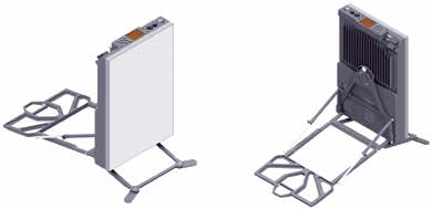
PCB antenna arrays with fixed beams can use mechanical positioning systems in the same manner that has been used with parabolic reflectors. One significant difference in the system architecture is that the feed network of a printed antenna array is typically located behind the radiating elements, whereas for a parabolic reflector it is placed in front of the overall assembly, making the overall form factor similar in operation, but somewhat more discrete due to the elimination of the RF feed network installed on a boom.
This form factor of a PCB antenna array (without the need for a feed boom) makes it an excellent choice of system architecture for a manpack solution. For example, a printed antenna array can be very small with hundreds of elements designed for receive only, or both transmit and receive functionality and not require a boom assembly for operation. This helps make the manpack antenna small and light to carry, and easy to deploy and manually point using features such as adjustable-height fold-out legs to optimally position the antenna for full horizon-to-horizon coverage.
For an aircraft, a PCB array antenna can be fabricated in a manner that is exceptionally well suited to the aircraft’s structural form factor, and this is true for both smaller and larger sized arrays. A conformal shape would allow for a really low profile aerodynamic radome to be placed over the antenna such that the overall assembly does not create excessive drag during flight. That said, a fixed beam conformal antenna typically is not meant to be steered mechanically and thus will have limited look angles. A better solution for an aircraft is a short and wide flat panel with conventional mechanical positioning so that the flat panel antenna can be tilted to send or receive a signal from a satellite at or near the horizon.
A PCB antenna has the advantage of being easier and more cost effective to manufacture than waveguide based counterparts. It also can be made conformal for certain applications.
The distinct disadvantage of PCB antennas is that PCB based systems tend to be lossy when compared to the air-filled waveguide components of a conventional parabolic reflector and feed system. The losses may be less significant when utilizing PCB based flat panel technology for LEO and MEO applications, whereby freespace loss effect is reduced due to the closer distance of the terminal to satellites in low or medium Earth orbit.
Active Electronically Steered Array Antennas
Active Electronically Steered Antennas (AESAs) are array antennas with each element having an independent solid state transmit and/or receive module. As such, each element can independently point to or track a satellite for transmit or receive, or collaboratively with other elements to create larger beams and increase gain. With one AESA, an operator can use the antenna’s control system to direct elements to point to multiple satellites simultaneously. And as all RF energy is directed with electronics, these antennas typically have no moving parts.
AESAs offer some very distinct advantages when compared to conventional parabolic reflectors. First, with few or no moving parts, AESAs do not experience the wear and tear that normally would be induced on those components that may dictate the functional life of the antenna. This is particularly important for LEO and MEO applications, as parabolic reflectors require constant movement as satellites are tracked as they move from horizon to horizon. This may even require multiple parabolic antennas, depending on how quickly the positioning system can repoint once a satellite passes out of view.
Another key AESA advantage is the ability to repoint almost instantaneously when compared to the slew rate of a parabolic reflector, which is key for tracking multiple satellites in LEO and MEO orbits. Additionally, the LEO or MEO distance reduction, as compared to GEO, makes losses in PCB materials less problematic, with high data rates still possible.

For GEO applications, however, AESAs do not offer much of an advantage. Traditional parabolic antennas with mechanical positioning systems typically operate with limited movement to maintain peak after the initial pointing is complete. As such, mechanically positioned antenna systems experience very little wear and tear and are optimal for GEO applications, so AESA technologies are not necessary.
A significant challenge for AESAs is the characteristic roll-off or reduced gain that occurs as the beam is pointed 60 degrees or more away from boresight. Because AESAs experience reduced gain as this low look angle pointing occurs, it necessitates multiple AESAs to form a complete field of view. For example, on a ship, multiple antennas would be required encircling and on top of the mast to provide complete coverage from any direction. It is possible that the collective of these antennas can be combined to produce an overall more robust data link to a single or even multiple satellites simultaneously.
Another much-anticipated application for AESAs is operation on a moving vehicle. If the vehicle is moving in a relatively stable direction in an open area — east to west across the state of Kansas for example — an AESA should work really, really well. But a vehicle driving in an area with limited visibility to the southern sky, such as an area with steep terrain, will experience significant signal outages. In this environment, a combination of mechanical steering and or multiple antennas would enable better overall signal management.
The PCB-based manufacturing process for AESAs makes this technology well suited to high volume manufacturing. But the PCB materials for Ku- and Ka-band are currently still expensive when compared to conventional PCB materials.
Other Electronically Steered Antennas
Another promising new technology incorporates the use of metamaterials. This solution uses tunable elements which scatter radio frequency energy when the elements are activated to generate a holographic beam. The beam is directed by the elements that are activated, which enables continual beam direction or immediate change in direction as required to maintain a satellite signal. As with other flat panel technologies, the range of steering is limited with one antenna, so the need for one or several antennas operating collaboratively will be determined by the application.
In conclusion, the demand for flat panel antennas is being driven by form factor, few or no moving parts, and communications on the move applications. And the new flat panel antennas coming to market now or very, very soon are fueled by amazing new technologies to meet these demands. Though parabolic and other mechanically steered antenna systems are robust and well-suited to many applications, the versatility of flat panel antennas will create new markets and new applications that have yet to be imagined.
Ian Timmins, Ph.D., is the Principal RF Engineer at AvL Technologies. Prior to joining AvL, Ian was VP of Engineering for Optical Cable Corporation’s Enterprise and Harsh Environment lines of business. He also previously held technical roles with Dell Computer Corporation, Cisco Systems and COM DEV Space Group.

Ian holds a Ph.D. in Electrical Engineering and is an adjunct professor with Western Carolina University.
Krystal Dredge is the Director of Marketing for AvL Technologies. Krystal has 15+ years of product marketing experience in satellite and wireless communications, and most recently worked at Honeywell and EMS Defense & Space Systems in Atlanta prior to joining AvL in 2012. She holds a BSJ degree in Journalism from the University of Kansas and an MBA from Wichita State University.