Satellite communication systems are driven by demands for increased data rates. Many satellite communication systems operate at microwave frequencies, such as X-, Ku- and Ka-bands, which help support a wider modulation bandwidth, increase capacity, and enable the use of smaller antennas. The increase in bandwidth, coupled with high operating frequencies, creates significant challenges for RF engineers who are testing a satellite system, module or component.
This article describes typical satellite applications that require power measurements as well as important factors to consider when selecting power meter and sensor solutions. The article also explains how these solutions can help simplify your work, and improve accuracy, reliability and test coverage.
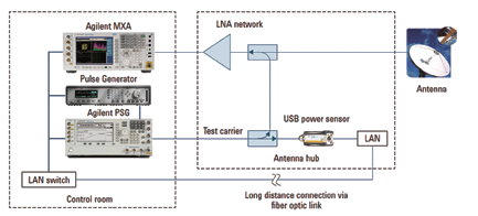
Figure 1. Typical test setup for continuous monitoring of the received power at a satellite antenna tower
Satellite Applications
Power measurements are critical in conducting satellite-related tests. To illustrate this, the following sections describe three major applications where obtaining power measurements are required.
Continuous monitoring of power received at a satellite antenna tower. Due to the long distance between a satellite and Earth, the signal received at the Earth station is usually very weak (below -100dBm). The condition can worsen with weather conditions such as cloud cover, humidity, and extreme temperature ranges that cause high atmospheric attenuation.
Antenna misalignment can also result in power degradation. Continuous remote signal monitoring is important to ensure that the received signal-to-noise ratio is high enough so the communication link can function properly. A spectrum analyzer working together with a power sensor can help to ensure accurate measurements are obtained.
Satellite manufacturing test. Before a satellite is launched into space, it needs to be tested in a thermal vacuum chamber in order to simulate space’s various extreme environmental conditions. The tests last for several months, running 24/7. During this time the chambers are cycled through hot and cold temperatures and other environmental conditions. Ports on the side of the chamber allow various test equipment, in numerous racks, to be connected to the satellite within the chamber.
Power measurement is very important during the testing stage as it monitors the output power of the transmitters and detects any instability, power spikes, or glitches. Up to 20 power meters and sensors can be connected simultaneously to the satellite in order to perform comprehensive testing over the Ku- and Ka-bands. Power measurements are polled once per second to ensure stability.
A strip chart recorder is connected to the power meter’s recorder output to record the data. If the transmitted power starts to vary, the test software shuts down the satellite to prevent damage.
With a test cost of close to $1 million per day, it is critical to ensure that all measurements are done correctly and accurately.
Satellite component test. Traveling wave tube amplifiers (TWTAs) and repeaters are key components of a satellite communication system and require accurate power measurements. TWTAs are used as amplifiers in satellite transponders when the input signal is very weak and the output signal requires higher power.
TWTAs are commonly used in a satellite due to their wide frequency coverage and high power capability. All TWTAs need to be tested to ensure that they can generate sufficient output power for the satellite transponder to function properly. Repeaters, on the other hand, are used to amplify and retransmit the signal at another frequency.
Each repeater acts as a receiver, frequency translator, and transmitter.
Sometimes called a transponder, a repeater typically consists of a low noise amplifier, a mixer or local oscillator, and a high-power amplifier such as a TWTA. As the receiver and transmitter in the repeater operate at the same time and in close proximity, careful testing needs to be carried out to ensure that the transmitter does not interfere with the receiver.
Power Meter + Sensor Selection Considerations
Due to a wide variety of requirements as illustrated, careful considerations have to be made to select the appropriate power meter and sensor. Below are some key considerations.
Frequency range: Many satellite communication systems operate at microwave frequencies identified in bands, such as the X- (8 to 12GHz), Ku- (11 to 15GHz) and Ka- (18 to 40 GHz) bands. It is important to select a power sensor that covers the correct frequency.
Long-term, remote monitoring: In satellite applications, whether they involve remote monitoring of a satellite antenna tower or testing a satellite in a vacuum chamber, the distance between the control room to the actual measurement point can be several hundred feet. Conventional power meter and sensor solutions are limited by a 200-foot maximum cable length.
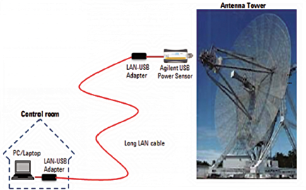
Figure 2. The maximum cable length of a USB power sensor can be extended up to 90 meters with a network or USB extender.
A USB power sensor comes with a five meter cable, however, this can be extended up to 90 meters with a network USB hub or USB extender. The sensor must offer long-term data logging of up to a year and be capable of alerting the user when power limits are violated. RF amplifiers in the satellite generate multiple tenths of kilowatts of RF power making it important to shut down the amplifiers when power levels are detected to be over the limit to prevent catastrophic failure or damage.
Zero and calibration: Access to the sensor is not always possible during remote monitoring of a satellite antenna tower or testing in a vacuum chamber. The sensor must be capable of performing accurate, long-term testing remotely.
Features such as internal zero, calibration and excellent long-term drift performance must be considered during the selection of the right power sensor. With a built-in DC reference source and switching circuit, a sensor with internal zero and calibration allows users to perform zeroing and calibration while the sensor is still connected to a DUT. This feature removes the need to connect and disconnect the sensor from an external calibration source and reduces test times, measurement uncertainty, and wear and tear on the connectors. The sensor can run independently in the satellite terminals for many months.
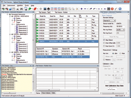
Multi-channel operations: A USB power sensor, due to its compact, faceless form factor, comes with companion software. It is important to choose a USB power sensor with software that is able to control and display the measurements of multiple sensors (up to 20) simultaneously. The software allows users to continuously monitor many different satellite transmitters at the same time and to perform mathematic operations, such as ratio and delta, between channels.
Performance over temperature: During comprehensive testing in the vacuum chamber, the satellite will be subject to extreme temperatures tests. It is crucial that the power sensor comes with built-in temperature compensated calibration factors to ensure that the measurements are accurate over a wide temperature range. Correction factors are stored in the sensor’s memory to correct for variations due to frequencies, power levels, and temperature.
The sensor’s built-in thermistor detects ambient temperature changes so that the right correction factor will be applied to compensate for any temperature-related drift. This will ensure that the USB power sensor is able to maintain high accuracy over a wide temperature range.
Type of measurements: Typical satellite performance monitoring requires simple average power measurements that are offered by most power meters or sensors. A built-in recorder output aids in archiving measurement results. The recorder output can be activated to output a voltage proportional to the measured average power, over a range of 0 to 1 V. For troubleshooting problems, connect to a plotter or strip chart recorder in order to print out a history of the measurements.
Avoid Dramatic Consequences
Satellite testing, whether it is for components, modules, or the whole system, is growing increasingly complex, and demands high accuracy and reliability. Defects and non-conformance can lead to dramatic consequences.
Manufacturers must deliver high quality, reliable products to effectively test satellites and meet the stringent expectations of customers. Agilent, with its 50-year history of producing high quality power measurement tools, offers a wide variety of power measurement equipment that is ideal for accurate and reliable satellite testing.
For additional details about recommended power measurement solutions for satellite testing, read the related application note at the Power Measurement Hints and Tips page (www.agilent.com/find/rfpowertips).