After 30 years of experimentation and something of a false start by the telecom industry in the 1990s and early 2000s, Ka-band satellite systems are finally coming into their own.

HPA manufacturers have started to reliably provide the high power and bandwidth that broadcasters and Internet providers require, and providers of DSNG, maritime and airborne solutions are taking advantage of the light weight and smaller mechanical footprints that Ka-band affords.
This article examines the latest proven high-power amplifier (HPA) technologies currently available on the market.
TWTAs have been the overwhelming choice for satellite uplinks in frequencies above Ku-band for years, largely because Ka-band signals are susceptible to rain fade. Although periodic outages due to rain fade do not cause great concern to some communications service providers, they are unacceptable to broadcasters and Internet providers, which have taken up the lion’s share of the satellite communications market, as the applications they provide require signal availability at all times. TWTA manufacturers are able to provide the high level of power and bandwidth that these applications require, while solid state manufacturers can only provide practical solutions at lower power levels.
Nevertheless, there are some applications providing exciting opportunities for manufacturers of Ka-band BUCs and SSPAs. Maritime and airborne communications applications, which do not require high power to get signals back to large gateway antennas on the receiving end, are ideal for this solid-state product class.
Although signal loss, like rain fade, is a concern for communications providers who need high-power technology, opportunities do exist where the small size and light weight of lower power SSPAs and BUCs can be mounted directly to antennas, reducing signal loss.
Getting Started: Operational Considerations + The Link Budget
Several factors regarding amplifier selection can come into consideration during the system design phase. For example, designers must consider whether the operating environment is benign or hostile; what type of bandwidth the application requires; what the cost of ownership is; what the operations and maintenance requirements are; and, most importantly, how much linear power is required to close the link.
Achieving the required radiated RF power is usually a trade-off between antenna size and amplifier power capability. In most situations, more flexibility is afforded to the amplifier than the antenna, e.g., if more power is needed, it is usually cheaper to buy a more powerful amplifier than a larger antenna. On the other hand, if one large receive antenna is going to handle transmission from multiple sites, then more powerful amplifiers may not be necessary. If the amplifiers need to be sheltered due to a suboptimal climate or if outdoor maintenance is difficult, additional power will be required from the amplifiers to overcome the inter-facility link (IFL) losses that occur between the shelter and the antenna. After these factors are considered, the system designer can begin to make a comparison between suitable amplifier technologies.
Linear Power
Once the general properties of the amplifier have been established, the optimal linear power required for the user’s application must be determined and compared to what is available from the various types of technologies. There are generally three possible methods for defining linear power:
1) Spectral Regrowth (SR) for single carrier operation
2) Third-order Intermodulation Products (IM3) (for two to five carriers, typically)
3) Noise Power Ratio (NPR) for multi-carrier and high-order modulation operation (more than five carriers typically)
These different categories need to be further refined depending on the type of modulation used and where and how the intermodulation products are measured.
Efficiency + Operating Costs
If the initial link budget indicates that more than one type of HPA can fulfill the output power requirements, the user may next want to consider each amplifier’s operating costs, size and weight, capital cost, reliability and serviceability. One of the critical elements of any amplifier is its efficiency, which always manifests itself in prime power consumption and heat generation, both of which affect the weight and size of an amplifier. Comparisons of efficiency have always been made between TWTAs and SSPAs. The “winner” depends on the required RF linear power level for the application in question.
With the advent of GaN technology, SSPAs are a good choice at higher power levels than can be practicably achieved by GaAs SSPAs. However, TWTAs remain far more efficient than SSPAs at medium and higher power levels, thereby minimizing cooling requirements in the antenna hubs where most Ka-band amplifiers reside.

Ka-band evaluations are complicated by the aforementioned high waveguide IFL losses of up to 3 dB per 10 feet of waveguide. Realistically, no one would ever consider putting an HPA in a distant shelter, because of the resultant loss. Instead, nearly all Ka-band systems are designed with the HPA located within a few inches of the feed, and even then the resultant power loss can be 10 to 20 percent.
This physical constraint means that Ka-band amplifiers must be small and lightweight, since the hub space is limited and installation is usually done manually in a narrow space.
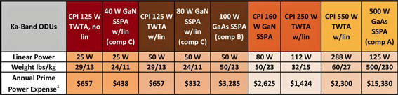
The chart above shows some of the most reasonable choices for Ka-band TWTAs and GaN SSPAs. In general, the TWTA is the best choice at linear power above 30W based on relative size and efficiency advantages.
Reliability + Life Expectancy
Typically, Ka-band HPAs are either installed in actively cooled radomes or hubs or are installed directly on antenna booms or hubs with full exposure to the elements. Naturally, the HPAs that are installed in cooled and protected locations will experience longer MTBF and longer life.
Based on CPI’s collection of extensive field data and more than 15 years of experience in Ka-band development, MTBF for a Ka-band TWTA is 4.6 to 10 years, with a lifetime of nine to 20 years, depending on the type of TWTA and where it is installed. These numbers do not include the 30 to 50 percent extended tube life that CPI’s patented LifeExtender™ technology is expected to deliver.
Though GaN SSPAs have not been in the field long enough to provide hard data, theoretical estimates based on reliability numbers provided by FET suppliers suggest that these products promise extremely good reliability, with excellent figures for MTBF and expected lifetime. It should be noted that lower power SSPAs will experience longer life and MTBF, because higher power SSPAs are the result of processes that combine devices in order to achieve their higher output; combining more devices will necessarily reduce reliability and expected life.
Technology Resource
Although the great TWTA v. SSPA debate is not fully relevant at the Ka-band frequency, due to the unique properties of each type of technology, there are still some instances where the user may be faced with a choice between the two technologies based on certain similar product characteristics. In general, however, HPA manufacturers’ products are well suited to the latest applications using Ka-band.
When deciding which technology to use, each user must weigh the pros and cons of vacuum-based TWTA technology versus solid-state technology, based on the requirements of the specific application in question. As a provider of TWTA and SSPA technology, CPI can be an excellent resource for users evaluating the best technology to utilize.
*Prime power expense is based on annual 24/7 operation, at $0.25 per kilowatt hour. This chart is generally arranged from low power to high power, and products are grouped by color at comparable linear power levels.
cpii.com/division.cfm/4