
State-of-the art satellite communication systems at the highest data rates are operated on the Ka-band. As transmission quality on Ka-band frequencies is heavily dependent on weather conditions, suitable system configurations need to be carefully planned and selected.
Ka-band Site Diversity configurations relying on DWDM RF-over-Fiber transmission systems and redundancy switching units represent best-suited solutions and ensure maximum system reliability and system availability.
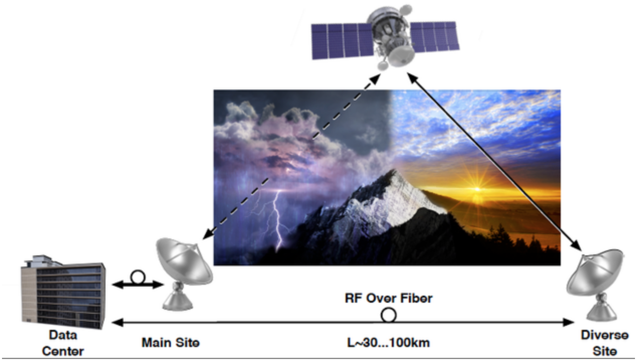 Figure1: Schematic drawing of Ka-Band Site DiversityKa-Band Schematic Drawing Ka-Band Transmission
Satellite communication systems represent a flexible and fast implementation platform for delivering versatile services including voice, data, or video signals. As satellite communication systems do not rely on existing communication infrastructures, like electrical or optical cable networks, basically all regions of the world can be reached independent of their remoteness or their specific geographical location.
Today, satellite communication systems are deployed with point-to-point and multi-point topologies around the globe for broadcasting, data, and multimedia services and cellular backhaul.
Traditional satellite communication is based on C- and Ku-band transmission frequencies. Today, orbital positions are highly congested and additional bandwidth can essentially only be provided by using additional frequency bands.
For that reason, Ka-Band satellites are gaining a high level of interest to face the increasing demand for higher data transmission rates. In addition to the provisioning of additional frequencies, satellite communication systems operating in the Ka-band offer several other benefits.
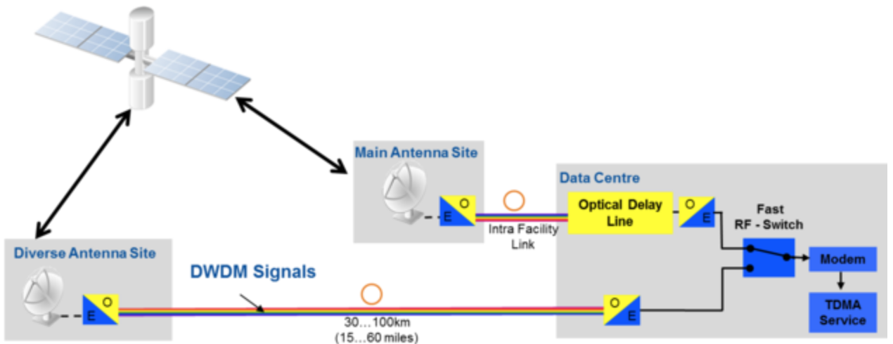
Figure 2. This is a detailed schematic view of a Ka-Band site diversity configuration.
First, the available frequency range in the Ka-band is about four times larger than for satellite communication in conventional C-and Ku-band.
Second, Ka Band transmission is typically employed with the usage of multiple spot beams, so-called ‘frequency reuse’ operation, that allows the transmission of different signals at the same frequency simultaneously to several geographic areas.
Third, the high transmission frequencies of Ka-band allow highly focused spot beams and smaller antennas, leading to economically efficient solutions at high data rates. Consequently, sate-of-the-art High Throughput Satellites’ (HTS) are operated in the Ka-band and provide data capacities exceeding 100 GBit/s per single satellite.
However, in addition to the undisputed advantages satellite communication system operated in the Ka-Band offer, they do face some challenges that need to be addressed appropriately through the installation of professional equipment and well thought out system configurations.
Ka-band transmission is severely degraded by adverse weather conditions. In particular, additional atmospheric losses due to rainfall exceed 30 dB for Ka-Band satellite transmission systems.
With such high atmospheric losses conventional fade margin approaches as adaptive-waveform techniques or adaptive-power control techniques are not sufficient for compensation. For reliable and highly available systems only Site Diversity configurations provide adequate solutions.
Figure 1 reveals the schematic view of a Ka-band site diversity configuration. The communication system is established by two antenna sites, a Main Antenna Site and a Diverse Antenna Site.
In case of adverse weather conditions, the data traffic is switched over to the Diverse Antenna Site. Typically, distance for separation of Main Antenna Site and Diverse Antenna Site is in the range 30 to 100 km. and the RF L-band signals are transmitted via optical fibers.
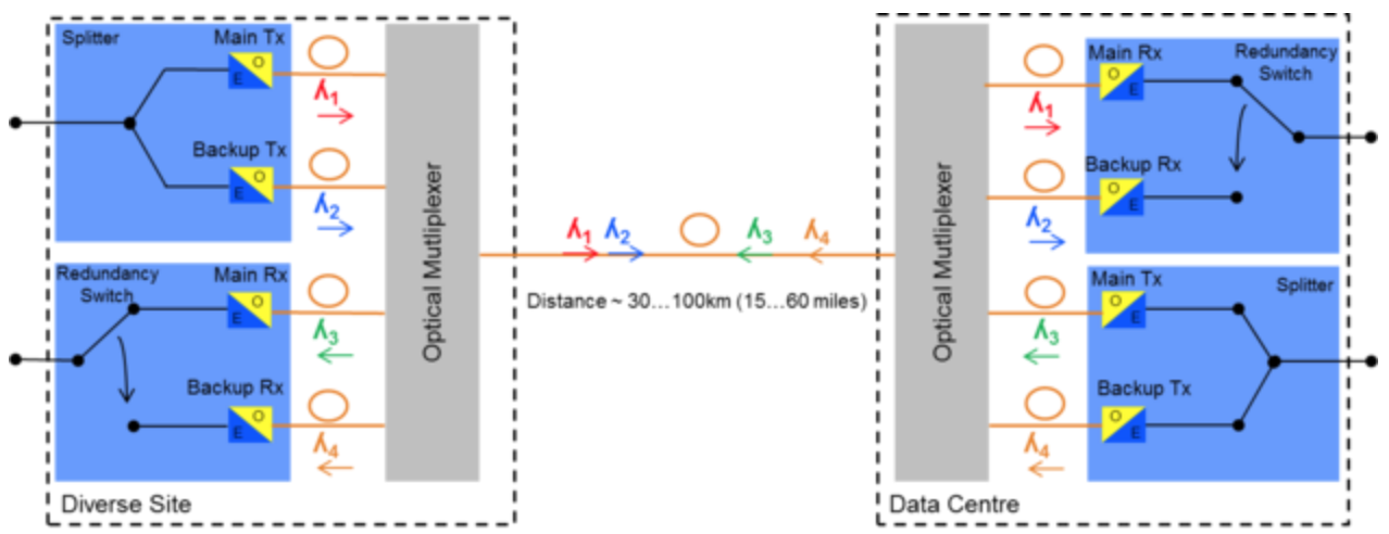
Figure 3. Detailed view of bi-directional Ka-Band Site Diversity configuration including equipment redundancyDetailed view of configuration including redundancy
A bidirectional optical link is used to transfer the signals between the Data Center and the Main or Backup Antenna Site, respectively. To relay the L-band signals between the Main Antenna Site and the Diverse Antenna Site, a fast RF switching unit is used to carry out switchover operations.
As Ka-band transmission systems are mainly operated with Time Division Multiplexed (TDM) signals, the time delay between Main Antenna Site and Diverse Antenna Site needs to be compensated.
To equalize this issue, an optical Delay Line with in steps of 10 ns. adjustable time delay is used in the optical link to the Main Antenna Site. To bridge the quite long optical distance between Data Center and the Diverse Antenna Site, an optical Dense Wavelength Division Multiplexing (DWDM) transmission system is employed.
This DWDM system enables the transmission of up to 49 RF signals over one optical fiber, thereby facilitating the transfer of highest data rates.
To further increase the reliability and the availability of the system, equipment redundancy can be applied in addition. Figure 3 displays the schematic view of a bidirectional optical link between the Data Center and the Diverse Antenna Site in 1+1 redundancy configuration.
For the 1+1 redundancy example, the RF signal is converted and transmitted by one main and one redundant transmitter module and received and converted by one main and one redundant receiver module.
In the case of a malfunction or loss of a main transmitter or main receiver module, the redundancy switch at the receiver side switches over to the backup equipment ensuring a signal transmission with highest possible quality and uptime.
dev-systemtechnik.com