The High Throughput Satellite (HTS) market is expanding, particularly with plans to launch Ka-band satellite services well into 2016. Ka-band frequencies have much narrower beamwidths than other popular bands, such as Ku-band.

As a result, Ka-band lends itself well to spot beams and frequency re-use—the principal reasons this band is so popular for high data throughput satellites. Inmarsat launched the first of its fleet of Global Express Ka-band spacecraft last December, which incorporates steerable spot beams. Preliminary GX tests show that high data throughputs are achievable on very small aperture terminals (VSAT).
The modern marketplace sets some tough design requirements; seeking increased throughput from ever-smaller satellite terminals with reduced size, weight and power requirements; constant pressure to increase manufacturing efficiency; reduce costs; and meet ever more demanding customer requirements.
In this article, we attempt to highlight some of the various technical challenges within the Micro-VSAT design and offer solutions to
those challenges.
The Micro-VSAT
VSATs are typically defined as a full duplex satellite ground station with a parabolic antenna that is smaller than three meters in diameter. The Micro-VSAT is typically a terminal incorporating an antenna that has the equivalent parabolic size of less than 60cm.
Designing low power, rugged, light, and high throughput Micro-VSAT systems presents numerous technical challenges. The words “low power,” “light” yet “rugged” with “high data throughput “ seem contradictory, and trade-offs are required among them. The high operating frequencies of Ka-band present further technical challenges, which can further compromise the size and weight of terminals.
Micro-VSAT terminals are often called “disadvantaged terminals.” This is because small terminals are limited in data throughput, due to the effective isotropic radiated power (EIRP) limitations at a system level and due to EIRP spectral density limitations defined by the various standards for operational use over the satellite. These limitations become more severe if the terminal does not meet the sidelobe requirements of the satellite operator. The reason for these imposed limitations is clear, it is important not to illuminate adjacent satellites and interfere with other users.
Link Budget
A link budget should be established for an operational scenario prior to the design of the terminals. A link budget is the accounting of all of the gains and losses from the transmitter, through free space to the receiver. The link budget accounts for the attenuation of the transmitted signal due to propagation, as well as the antenna gains, satellite transponder statistics, feedline and miscellaneous losses. From the link budget, two key figures for the Micro-VSAT system need to be determined:
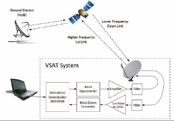
Figure 1. Typical VSAT system block diagram
1. The minimum EIRP required
2. The minimum G/T required
The EIRP is given via the following equations:
EIRP(W) = Power given out by an amplifier (W) x Gain of the antenna or,
EIRP(dBW) = Power given out by an amplifier (dBW) + Gain of the antenna (dB)
The antenna gain-to-noise-temperature (G/T) is a figure of merit in the characterization of antenna performance, where G is the antenna gain at the receive frequency and T is the equivalent noise temperature of the receiving system in kelvins.
G/T = Antenna Gain (dB) – System Noise Temperature (dB)
The noise temperature of the system is the summation of the antenna noise temperature and the RF chain noise temperature from the antenna terminal to the receiver output. Components such as the Low Noise Amplifier (LNA), Block Down Converter (BDC), waveguide and cables all contribute to the system noise temperature and negatively affect the G/T value. Minimizing the noise factor of the LNA and BDC blocks and any system insertion losses in order to maximize EIRP and G/T is important to accomplish.
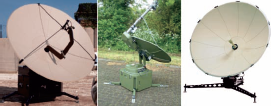
Figure 2 – Various GigaSat VSAT systems. From left to right; front feed antenna, offset feed antenna and centre fed antenna.
The terminal EIRP and G/T should be selected that yields a Signal to Noise Ratio (SNR) on the remote receiver (Hub) or terminal receiver side respectively, which is greater than threshold for the chosen modulation
and coding scheme to decode the signal error free in the worst of atmospheric conditions.
Reaching the desired EIRP is a trade-off between antenna size and the output power capability of the solid state power amplifier (SSPA). This leads to the first challenge when faced with designing the Micro-VSAT. Which antenna to choose?
The Choice Of Antenna Technology
There are two broad categories for micro-wave antennas used in VSAT systems:
1. Parabolic
2. Flat Panel

Figure 3. From left to right, Cassegrain and Gregorian antenna.
Parabolic Antennas
A parabolic antenna uses a parabolic reflector, a curved surface with the cross-sectional shape of a parabola, to direct the radio waves resulting in high directivity. There are essentially five main types of parabolic antennas:
• Axial or Front Feed
• Offset Feed
• Cassegrain
• Gregorian
• Center Feed
In the axial feed antenna system, the feed is located in front of the dish at the focal point. The energy from the radiating element is arranged so that it illuminates the reflecting surface. Once the energy is reflected, it leaves the antenna system in a narrow beam, resulting in high gain. This type of antenna is a widely used feed system for larger parabolic reflector antennas as it is easy to implement. However, the feed and its supports do block some of the beam, which limits the aperture efficiency to between 55–60 percent. The feed is directed backwards, so spill over sidelobes caused by the portions of the beam that miss the reflector are directed downwards to warm Earth. This results in higher antenna noise temperatures (lower G/T).
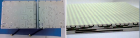
Figure 5. From lef to right: Microstrip antenna and complex multi-layer strip-line distribution.
With the offset feed antenna, the reflector is an asymmetrical segment of a paraboloid—the focus and feed are located to one side of the dish. The purpose of this design is to move the feed structure out of the beam path so it does not block the beam. The feed horn should be optimized for the focal point to dish diameter ratio (F/D), otherwise it either won’t fully illuminate the entire dish, or in receive will “see” around the edges of the dish and pickup terrestrial interference. This type of antenna offers superior sidelobe performance and enhanced aperture efficiencies.
In the Cassegrain antenna design, the feed is located on or behind the dish and radiates forward, illuminating a convex hyperboloidal secondary reflector at the focus of the dish. The radio waves from the feed reflect back off the secondary reflector to the dish, which forms the outgoing beam.
This has the advantage that the waveguides and “front end” electronics do not have to be suspended in front of the dish. The feed is directed forward, so spill over sidelobes caused by the portions of the beam that miss the reflector are directed upward toward cold sky, rather than downwards to warm earth. This results in lower antenna noise temperatures (better G/T). The second reflecting surface allows for opportunities to tailor the radiation pattern for superior sidelobe performance. The aperture efficiency is of the order of 65–70 percent, however, the feed horns must have a narrower beamwidth (higher gain) and, hence, are longer.
The Gregorian design is similar to the Cassegrain design except that the secondary reflector is concave, (ellipsoidal) in shape. An aperture efficiency of more than 70 percent can be achieved because the system is able to provide a better illumination of the entire reflector surface. Both the Gregorian and Cassegrain antenna architectures present packaging challenges on smaller VSAT designs.
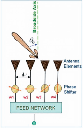
Figure 4. Flat array of radiating elements
The center-fed design is commonly used in Micro-VSAT designs due to the ease of design and packaging. However, this design often results in poorer sidelobe performance, particularly for small antennas (<65cm) and the aperture efficiency can be as low as 50 percent.
Flat Panels
Flat panels consist of an array of radiating elements. The individual transducer elements can each be independently driven. These probes or apertures are connected to specially adapted drive units that enable independent, simultaneous emission and reception along each channel. These units should also be able to affect, during emission and reception, the different electronic time delays for each channel.
Electronic pointing is based on the use of these electronic delays along the feed network to each of the apertures. Varying the delays or ‘phasing’ results in the user’s ability to point the beam in different directions without physically moving the antenna. Tactical terminals that are positioned remote from the operator may require this type of Electronic Steerable Array (ESA) capability to point to multiple satellites. (See Figure 4.)
Although the variety of types of radiating elements can be quite high, some of the most typical are:
• Printed on substrate (Microstrip and Stripline)
• Horns
• Opened waveguides
• Metal plates
• Slotted waveguides
• Metamaterials
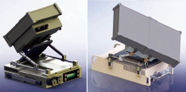
Figure 6. GigaSat Ka-band terminals using waveguide flat panels, with 20cm and 40cm antennas designed and manufactured by Micro-Ant LLC.
Micro-Strip antennas are good for low frequency applications. They are thin, small and cheaper to manufacture. However, at high frequencies, the losses become greater.
Strip-Line antennas are less lossy at higher frequencies and are common in antennas up to 15GHz (Ku-band). They are still relatively thin and incorporate multilayer systems.
Waveguide distribution of power yields ultra-low loss at high frequencies (Ka-band). However, they tend to be thick and expensive to manufacture due to the tight tolerances required. Large investments need to be made to find suitable production plastics and metallization processes to make the antennas light, rugged and to meet the tight tolerances required for suitable RF performance.
Metamaterials are man-made materials that defy conventional wisdom as to how radio waves behave when moving from one medium to another. In normal convention, when electromagnetic waves move from a less dense to a more dense material, they will be refracted towards the normal.
A metamaterial can have a negative refractive index. Using this concept, an antenna made from hundreds of tiny metamaterial elements can be
individually excited and phased together to focus the radio waves that hit it. Thus, an ESA is formed by using software to control the phasing of its component parts, bending the transmit and receive beams as required.
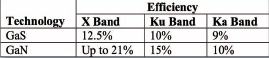
Table 1. Efficiency table of SSPAs
Parabolic vs Flat Panel
Flat panels are a good option when considering Micro-VSAT designs where the antenna size is less than 60cm. Superior side-lobe performance can be obtained with flat panel technologies by adjusting the way each of the transducer elements are driven. Flat panels are easier to package but are more costly to manufacture and are band specific. Different antennas would be required to cover different frequency bands and the incorporated technology may also differ considerably. Consequently, RF mounting to the desired power amplifier and LNB could differ between bands.
Parabolic antennas are cheaper to produce and can be multi-band by simply changing the feed, orthomode transducer (OMT) and RF chain. However, it is difficult to guarantee good performance over multiple and wide ranging frequency bands.
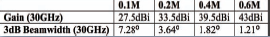
Table 2. The gain of various different antenna sizes and associated beam-width at Ka-band
For superior performance the parabolic antennas are often tuned for a specific band. The mounting and packaging structure can remain the same. For a small and lightweight pack down, as required in a Micro-VSAT design, the antenna would need to be segmented into smaller assemblies. The segmentation process can affect the shape of the parabola, particularly if the dish is not assembled correctly and will, therefore, negatively affect the side lobe performance. The equally obvious disadvantage is the requirement to assemble the system prior to use.
Solid State Power Amplifiers
The Solid State Power Amplifier (SSPA) is the most power inefficient component in the system. Micro-VSATs will typically use SSPAs at powers up to 30W. There are two types of semiconductor technology used within the SSPAs; Gallium Arsenide (GaS) and Gallium Nitride (GaN). Power efficiency is defined as the conversion of input power to usable output power. GaN devices are more power efficient (please refer to Table 1) and are able to withstand much higher baseplate operating temperatures and so lessening the heatsink requirement. They are becoming more prevalent in low power X- and Ku-band systems. GaN semiconductor technology is starting to become available in low power Ka-band systems, albeit at a much higher cost to the user
Due to the SSPA power inefficiencies, small increases in power can have dramatic effect on the size and weight of the amplifier in order to dissipate the extra heat generated. This will also have the impact of necessitating a larger DC power supply within the VSAT terminal which has its own power inefficiencies (typically 86 percent). This has the net effect of shorter battery life and the need for larger heatsinks to adequately cool the larger power supply unit (PSU).
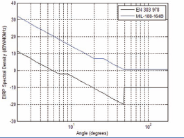
Figure 7. Ka-band EIRP spectral density limitations.
Sidelobe Performance + EIRP Limitations
Antenna design should be such that most of the radiated energy is formed in the direction of the target. Inevitably, some of the energy will spill into other directions around the antenna, forming what is known as sidelobes of energy. The job of the antenna designer is to minimize these sidelobe incursions. Antenna sidelobe performance is measured at a far-field range.
The smaller the antenna, the wider the beamwidth of the radiated energy in the direction of interest. Table 2 shows a table of the gain of various different antenna sizes and the associated beamwidths at Ka-band.
At Ka-band, there are two popular standards for defining the EIRP spectral density limitations; ETSI EN 303 978 for commercial frequencies and MIL-188-164B for Government frequencies. The graph shown in Figure 7 summarizes those limitations.
Figure 8 (on the following page) shows an indicative sidelobe performance of a 20cm flat panel antenna and its EIRP limitation according to MIL-188-164B.
It is clear to see from Figure 9 (following Figure 8) that the limitation with the 20cm antenna is not defined by its sidelobe performance, which is actually good, but by its beamwidth. With this antenna, it is possible to safely transmit 5W of power in a 100kHz bandwidth.
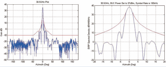
Figure 8. Indicative 20cm flat panel antenna sidelobe performance and its EIRP spectral density limitations.
The commercial requirements for Ka-band define a further 20dB reduction, which will result in a required spreading of the signal across a bandwidth 100 times that of the 100kHz needed in the military band for the same power. This would also incur significant bandwidth costs from the satellite operator. Therefore, careful consideration must be given to the terminals EIRP limitations when considering antenna size and required SSPA power.
System Features
Little has been said on the choice of a modem. This is because the modem selection can depend upon the target application, user requirement and customer base infrastructure. There are many board level modems that are suited to Micro-VSAT design and for a truly flexible terminal that can cover a wide range of applications and markets, the emphasis should be to allow adequate space for a wide range of modems and, more critically, a design that allows the modem to be adequately cooled. The latter statement should not be underestimated.
Another important aspect of Micro-VSAT design is to provide the user with assistance in pointing the antenna to the satellite. The primary aim is to get the user to acquire and fully peak onto the satellite in as little time as possible with minimal training or technical expertise. To facilitate this, it is necessary to have three primary sensors on board the system connecting to a central processing unit (CPU); that is a GPS, a Compass and Inclinometer.
With these three sensors, the CPU can know the current location, heading and inclination of the antenna and calculate where the user should point the terminal in order to acquire the satellite. This is done with the use of some simple trigonometry. The control card can incorporate an editable satellite data base in order to provide simple selection of the target satellite. A more detailed block diagram of a Micro-VSAT design can be seen in Figure 9.
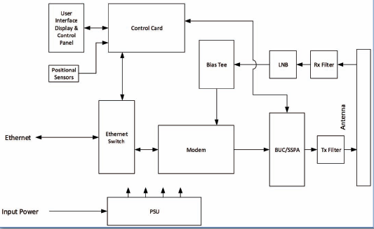
Figure 9. Micro-VSAT block diagram
Careful consideration must be employed when selecting the control card, which should be powerful enough to add features such as web-servers, network management options and a colorful graphical interface (GUI). The software code should be portable to other control platforms to mitigate obsolescence. The control card should also contain a mixture of high and low level programming for complex code development and interface to low level peripheral devices respectively (i.e., keypad entry, various displays and general purpose IOs for additional flexibility). Of course, the card must be small, of rugged design, draw minimal power and cope with extended temperature ranges (-20 to +80). There are many platforms available on the market.
Tight Integration Vs. Modular
Tight integration of all of the electronics offers the lightest weight, most power efficient and smallest design. Commonalities within the system
can be shared. The fully integrated module is less flexible in being able to change frequency bands and powers and less easy to service. In contrast, the modular approach is highly flexible, easy to service and allows the user to change bands while in the field. However, this flexibility also results in a less efficient design in terms of power, weight and size.
Material Properties
Material properties and processing play a large part in the design of Micro-VSAT antennas. Depending on the component part, there may be a number of potentially conflicting requirements. Lightweight for easy manual handling, high stiffness for accurate antenna positioning and robustness for transit are common conflicts. Additional requirements include corrosion resistance, UV resistance, low friction (for gears and bearings), high friction (for brakes) and either RF transparent or reflective properties depending on the part. Common materials used may be grouped into metals, polymer and composite parts. Of the metals, aluminum and stainless steel are used for their light weight and corrosion resistance. Of the composites, popular choices are carbon fiber and glass fiber.
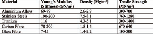
Table 3. Table of material properties
Carbon fibers can be molded into high stiffness, low weight parts but require tooling and skilled labor to manufacture the parts. Carbon Composites are RF reflective making them a good choice for parabolic reflectors. This composite material is also electrically conductive, which assists in meeting the various EMC regulations. Conversely, glass fiber is RF transparent while also being rugged, making it a good choice for a radome design.
Polymer parts are relatively low density and can have good bearing properties, but are generally not stiff, so care is needed when they are used in structural applications. Polymers are often a good choice for large volume manufacture. The general requirements can be broken down as follows:
• Stiffness – antenna pointing
• Rugged/robust – operator handling, transit
• Weatherproof – corrosion/UV resistance
• EMC shielding
• Lightweight – airline and defence requirements
Conclusion
Many factors need to be considered when designing lightweight, highly portable, rugged Micro-VSAT systems. The link budget is key for determining the minimum required EIRP and G/T which set a lower limit on the size of the antenna and amplifier combination. An EIRP spectral density analysis should be performed which will also affect the choice of antenna size and type.
Every dB of performance counts within the system and so the choice of antenna technology and SSPA mounting position are crucial. The LNA and BDC and receive waveguide components have a crucial impact on the terminal G/T. The packaging challenges should also be factored into the design and often there is a trade-off between the “micro” packaging of the system and its performance.
System power inefficiencies are also a critical factor in determining the size and weight of the Micro-VSAT. Higher transmit powers from the SSPA result in higher input powers and cooling requirement’s. Fanned systems may not be an option in military applications and are often a common point of failure within a system.
Finally, the choice of materials is the next crucial deciding factor in the VSAT design. A composite solution can often present the lightest weight, most rugged solution but it is labor intensive to produce.
There are many trade offs to consider, all of which make the Micro-VSAT design a complex one. Advances in semiconductor and metamaterial technology will, no doubt, aid in bringing the size and weight down of future terminals.
To produce a Micro-VSAT that fits all requirements is difficult, as user needs vary significantly. For some customers, size and weight are paramount (airline carry-on, or hold checkable); for others, the priority is extended battery life, or ease of use, modem flexibility, or a whole host of other specific requirements.
Flexibility of design and configuration are essential. Ultra-GigaSat Electronics has vast experience in producing terminals that are tailor-made to meet individual customer requirements, for commercial, broadcast, government and defence applications.
If you wish to discuss your specific requirements, please contact us at satnewsinfo@ultra-gigasat.com.
For additional details, please visit the company’s infosite at http://www.ultra-gigasat.com/

About the author
Andy Slaney is Technical Director at Ultra Electronics, GigaSat, specializing in the design and manufacture of satellite and terrestrial communication equipment. He has more than 20 years design experience in the communications industry with a proven track record for fast-tracking product growth and innovation within many organizations. Andy holds two degrees which include a Bachelor of Engineering (First Class) and a PhD in communication system design.