
Hiltron’s strategy as a systems integrator has long been to source from third-party suppliers whenever products and components of high quality and reliability are available on the open market. If these products meet these criteria, then the company internally develops and manufactures the required devices.

Becoming apparent during the early 2000s, the communications industry was in serious need of a high precision, motorized satellite antenna mount that was capable of accommodating transmission/reception antennas of up to 3.7 meters in diameter, preferably at an accountant-friendly price.
The Hiltron management team went into a Wouldn’t It Be Nice If mode and, in consultation with customers from the broadcast, telecommunications, aerospace, scientific and defense markets, mapped out a design that would potentially meet a wide range of applications.
The original concept was to include high-grade drives for azimuth, elevation as well as a polarization drive. This would need to be controllable by Hiltron’s standard HACU antenna positioning software running on a desktop or a portable PC. A combined head and drive would be incorporated, forming a three axis motorized mount with up to 240 degrees of azimuth adjustment, 90 degrees of elevation adjustment range and fully adjustable polarization.

A choice of support plates would allow the attachment of different types of reflectors, obviously a vital concern to ensure the greatest possible mechanical compatibility. The rotating pedestal mount would need to made of corrosion-protected hot-dip galvanized steel to provide the required rigidity and weather protection. The azimuth and elevation drive motors would operate through a reduction gear.
Much consideration was given to the azimuth movement. This would ideally be accomplished via an axle bearing with a drive motor allowing the entire satellite arc to be covered from any position on the planet. The elevation movement would be via a jackscrew with a further drive motor.
This design and the use of true angle indicators (optical encoders) would provide highly reliable and very accurate positioning far beyond the stability of commercial grade actuator devices. Low backlash was a vital requirement requiring high rigidity in the construction. The mount would need to be capable of operating in winds of up to 125 km/h and survive up to 200 km/h, subject obviously to the base construction.
The Control System
Ethernet-based control from a remote PC is obviously an important aspect for any modern SATCOM product or system. Hiltron’s established ACU software would allow the satellite mount to be monitored and operated via IP-based control from a PC running a graphic user interface compatible with standard web browsers.
The control GUI would be configured to display all the information required to set and maintain azimuth, elevation and polarization, including current position and target position plus a database of potential accessible satellites. Once a satellite was selected, ACU would allow precise access parameters to be calculated at the press of a single button. The ACU would also need to be compatible via SNMP with a remote monitoring and control system.
The developed specification called for azimuth and elevation to be adjustable at up to three different speeds. The mount was be available in several versions to match applications, such as inclined orbit tracking, operation across an extended temperature range, integration of a de-icing system in the ACU housing, and so on.
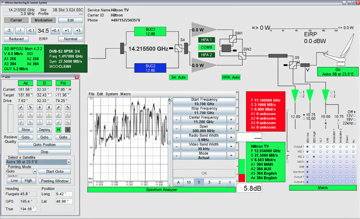
Figure 1. Hiltron HMCS monitoring and control overview GUI.
HMAM & SORBAS
From initial discussions based on the above deliberations, the Hiltron team advanced to full-scale technical planning, structural design and then first assembly. Within a matter of weeks, there was a full working prototype of the Hiltron Motorized Antenna Mount or HMAM.
After several months of field tests, HMAM was demonstrated in June of 2010 at Broadcast Asia and, three months later, at IBC. The antenna has since become a core element of SORBAS SATCOM product family. These include the Hiltron HMCS monitoring and control software (please see Figure 1 above), HCS universal control unit, HSACU satellite antenna control unit, HMAM three-axis motorized satellite antenna mount and HDCU de-icing control unit.
Central to SORBAS is the HCS-Core (shown in Figure 2 to the right), which is used as a monitoring and control element for tasks such as switching and monitoring of downconverters, integrated receiver/decoders, digital video broadcast encoders, high-power amplifiers and waveguides. HCS-Core is available in 2U high full-rack-width and half-rack-width versions.
The full-rack-width model can accommodate as many as 16 modules and is Hiltron’s largest and most versatile satcom controller to date. The current range of cards includes a monitor, control and power supply for fiber optic devices, a fiber-optic switch, LNB redundancy systems for C- and Ku-band, HPA redundancy control, redundancy for DVB MPEG encoders/modulators/IRDs and a generic monitoring and control module.
The HDCU-E element of SORBAS is a combined ice-sensing and dish heating controller for use with large satellite antennas and is capable of handling up to 450 kilowatts of power across multiple heating groups.
Each group is divided into three independently controlled heater arrays. Each array, in turn, feeds up to three antenna heater circuits. A four-group configuration, for example, allows control of 12 arrays addressing a total of 36 heating circuits. This modular control approach permits easy configuration of parameters such as antenna size, number of heater pads and the power requirement of each pad. Snow detection is via a reflective sensor with a polarizing filter.
Each heater circuit is individually supervised and controlled via user-adjustable minimum and maximum thresholds. Sequential switch-on is performed within the controller to prevent rapid changes in current load when the antenna heating process is activated or deactivated. Sequence timing is user-configurable.
The Hiltron HACU is designed to control three-axis motorized antennas. The antenna control unit and associated motor-control electronics are contained in an IP65-rated weatherproof outdoor housing with a hinged front access port secured by dual key screws.
The HACU can be operated from a PC running a graphic user interface compatible with standard web browsers. The control GUI displays all the information required to set and maintain azimuth, elevation and polarization, including current and target positions plus a database of potential accessible satellites.
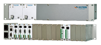
Figure 2. Full-width 2U version of the Hiltron ComSys-Core (HSC-Core) universal satellite communications controller.
LEO & MEO Applications
HHAM—on its own or integrated into a SORBAS system—has a wide range of applications. These include reception of LEO and MEO satellite signals, test and measurement tasks, redundancy antenna control for IPTV, satellite newsgathering, downlinks and uplinks. Figure 3 shows a Hiltron HMAM with 2.4 meter antenna configured for LEO mission.
Launch and Early Orbit Phase (LEOP) is one of the most critical phases of a satellite mission and demands steady monitoring and control of the parameters from various subsystems 24 hours a day from multiple locations. An antenna system with high accuracy pointing and fast positioning with high reliability is essential. HMAM forms part of a recently completed system which consists of three stations located around the world getting enough visibility to satellite for LEOP mission.
The existing HMAM design has been tailored to the LEOP requirements. The HMAM has been fitted out with a 2.4 meter antenna and with two different fixed feeds which enable the reception of C-and Ku-band circular polarized signals without need for mechanical movement of the feeds. Both feeds are localized as near as possible to the focal point of the antenna structure. To switch over the bands, it is necessary to move the azimuth to different angles to receive the same satellite.
Precise calibration of antenna direction is performed by the ACU. This is one of the important requirements for the LEOP mission. Directional accuracy and the controllable antenna travel speed are outstanding features of the HMAM. The absolute pointing accuracy for azimuth and elevation angles is better than +/- 0.05 degrees and the relative pointing accuracy is better than +/- 0.02 degrees within any operable angle range of +/-2 degrees.
In addition to the high accuracy requirement, the antenna needs to be pointed quickly to the target. This requirement is fulfilled with a maximum elevation drive velocity faster than 1 degree/second in the elevation range 20 to 80 degrees. Maximum azimuth drive velocity is faster than 4° degrees/second over the total azimuth range (240 degrees). These high specification requirements for accuracy and controlled speed are essential to fulfill the challenging task for LEOP mission applications.
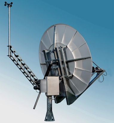
Figure 3. Hiltron HMAM with 2.4 meter antenna for LEOP mission.
The HMAM subsystem for this project will be controlled remotely and is equipped with a wind sensor for antenna protection moving the dish automatically to survival mode for wind up to 200 km/h. As an option the HMAM can withstand winds up to 330 km/h.
HMAM-IOT
The Hiltron HMAM-IOT variant incorporates inclined-orbit tracking. To conserve guidance propellant, older satellites are allowed to drift further from their nominal target position than during their main service life. Operators therefore offer greatly reduced transponder capacity pricing. The HMAM-IOT’s advanced tracking capabilities enable the antenna to follow these variations in position and is the ideal solution for cost-efficient uplinks on inclined-orbit satellites.
HMAM-Ka
IBC 2013 saw the introduction of world’s first triple-axis motorized 2.4 meter, receive-only, Ka-band antenna with switchable linear and circular polarization. The HMAM-Ka was developed in close co-operation between Hiltron and ESA Microwave, based on a newly designed Ka-band polarizer. Ka-band includes the 21 gigahertz band which is becoming increasingly important for satellite downlinks. The HMAM-Ka can accommodate antennas of up to 3.7 meters diameter and is fully compatible with Hiltron’s standard HACU antenna positioning system.
hiltron.de/
About Hiltron
Hiltron is a globally active system integrator, manufacturer and distributor in the field of satellite and wireless communication. The company operates from modern, purpose-built headquarters near Stuttgart, Germany. The company is part of the Danmon Group, one of Europe’s leading suppliers of audio, video, transmission products and digital media solutions.