TWT technology continues to be a key player in the industry
As significant improvements continue to be achieved in high-power amplifier design, many claims are being made regarding the capabilities of each type of amplifier technology used in satellite uplink applications.
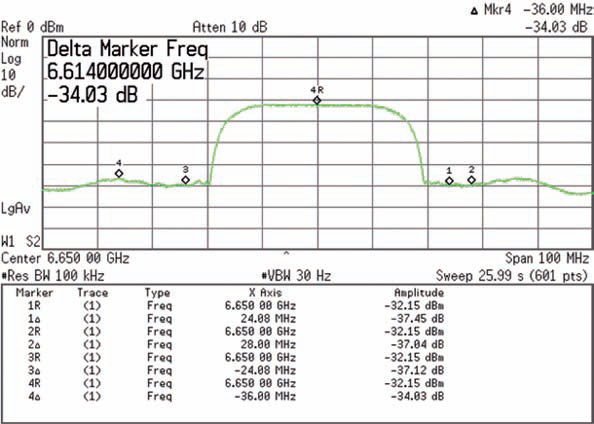
Figure 1: Spectral Regrowth
Many companies will extol the virtues of the amplifier technology they offer, while playing down the strengths of technologies they do not offer. SSPA manufacturers historically have been the boldest practitioners of this strategy, often making lofty predictions about how their products will kill off TWTAs, KPAs, or both. For example, in 2011, one manufacturer excoriated those who “clung” to the “energy-draining tube technology of the past.” In another advertisement from 2007, a manufacturer boldly announced a new line of “TWTA Killers,” claiming reliability, efficiency and linearity advantages over TWTAs. Industry pundits even wrote articles in the late 1980s that claimed the end of the klystron amplifier within five years. Today, we all know these claims are far from the truth.
TWT technology continues to be a key player in the industry, on the ground and in space, primarily because the technology has evolved and improved steadily over the years. Solid state technology has also made significant improvements. Low power (i.e., up to 200 W Psat) applications have largely become the territory of solid state.
In today’s market, “The Next Big Thing” is Gallium Nitride (GaN)-based solid state amplifiers which, like their Gallium Arsenide (GaAs)-based predecessors once did, present a new and interesting question in respect to their position against TWTAs and KPAs.

This article examines the relative merits of GaN versus tube technology, assesses recent claims made extolling GaN technology, compares technologies on a “like-for-like” basis, and draws conclusions about the most appropriate applications for each technology. Communications and Power Industries LLC (CPI) is uniquely qualified to provide this assessment, as we design and manufacture both solid-state and tube-based amplifiers, including GaN SSPAs, GaAs SSPAs, TWTAs and KPAs. To assist users in making an informed decision when evaluating amplifier technology, a balanced view will be provided for selecting the best amplifier technology for a specific application.
What Is GaN?
Solid State amplifiers use a series of combined Field Effect Transmitters (FETs) to amplify signals. These FETs are made of Gallium Arsenide or Gallium Nitride, which are compound semiconductors that together produce a covalent bond of eight electrons, yielding a large band-gap and high electron mobility.
GaN FETs first gained popularity in the early 2000s with the U.S. military for use in electronic warfare and radar applications. GaN technology is capable of achieving up to five times the amount of power of GaAs technology over the same bandwidth, necessitating less power less power combining and resulting in greater efficiency. GaN FETs are also capable of transmitting signals in all of the current and planned satellite frequency ranges. The result is an SSPA that is capable of more raw output power than one using GaAs FETs, which also makes more efficient use of prime power.
GaN SSPAs are inherently more reliable when they are used in exactly the same way as GaAs SSPAs. However, most GaN SSPA manufacturers have decided, instead, to produce smaller amplifier packages which typically have similar thermal margins to GaAs SSPAs. Thus, in practice, GaN SSPA reliability is approximately the same as that for GaAs versions.
What Advances Have TWTAs Made?
TWTAs have advanced considerably since they were first used for satellite communication uplinks 40 years ago. Ground-based TWTs originally used a single collector, necessitating amplifier packages that were large and relatively inefficient. The introduction of linearizers doubled the operational prime power efficiency by increasing the permissible RF operating point. Now, linearizers are relatively small and integrated into the amplifier enclosure. When multi-stage collector TWTs were introduced, this development almost tripled prime power efficiency. Today, all TWTs used in satellite communications have multi-stage collectors, resulting in more efficient and smaller amplifiers.
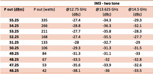
Table 1. IM3 When Measured at Varying Power Levels and Frequencies
CPI has made notable contributions to the evolution of TWTAs in recent years. One such significant advancement is CPI’s SuperLinear® TWTAs, which have nearly doubled efficiency again, keeping this class of amplifiers well ahead of other technologies. CPI also recently introduced technology called LifeExtender™ that considerably prolongs the TWT cathode life, significantly reducing maintenance costs.
When evaluating whether to use a TWTA or an SSPA, customers should exercise caution in reviewing marketing materials, as many SSPA manufacturers typically base their power-consumption, size and weight comparisons on older types of TWTAs. In doing so, they can overstate the attributes of their own products and unfairly denigrate the customer’s other potential options. This trick can mislead users as it does not provide a valid like-for-like comparison of what is readily available today from all amplifier technologies.
Klystron Power Amplifiers—Who Uses Them?
KPAs are a good choice for a single transponder, dedicated uplink application where link availability is of utmost importance. Some of the most popular applications for KPAs today are fixed broadcast and Direct-To-Home (DTH) television. These applications demand the ability to transmit at high power when necessary in order to overcome temporary high-environmental RF losses, such as rain fade.
KPAs are narrow bandwidth devices (usually less than 100 MHz) with multiple channels to enhance flexibility. Today, klystrons generally utilize multi-stage collectors for maximum efficiency. They can also operate at reduced beam voltage so that prime power is conserved during lower RF power operation, but remain ready to ramp up when higher RF power is required. Klystrons are generally regarded as the “workhorse of the industry” with MTBFs in the 200,000 hour range.
Getting Started: Operational Considerations + The Link Budget
Several factors regarding amplifier selection can come into consideration during the system design phase. For example, whether the operating environment is benign or hostile; what type of bandwidth the application requires; what the cost of ownership is; what the operations and maintenance requirements are; and, most importantly, how much linear power is required to close the link.
Achieving the required radiated RF power is usually a trade off between antenna size and amplifier power capability. In most situations, more flexibility is afforded to the amplifier than the antenna, e.g., if more power is needed, it is usually cheaper to buy a more powerful amplifier than a larger antenna. If the amplifiers need to be sheltered due to a suboptimal climate or if outdoor maintenance is difficult, additional power will be required from the amplifiers to overcome inter-facility link (IFL) losses that occur between the shelter and the antenna. After these factors are considered, then customers can begin to make a comparison among suitable amplifier technologies.
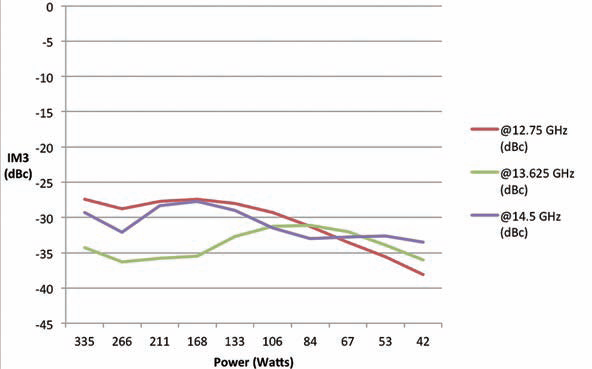
Figure 2. Comparison of IM3 at Various Frequencies
Linear Power
Once the general properties of the amplifier have been established, the required linear power must be determined and compared to what is available from the various types of technologies. There are generally three possible methods for defining linear power: 1) Spectral Regrowth (SR) for single carrier operation, 2) Third-order Intermodulation Products (IM3) (for two to five carriers, typically), and, 3) Noise Power Ratio (NPR) for multi-carrier and high-order modulation operation (more than five carriers typically). These different definitions need to be further refined depending on the type of modulation used and where and how the intermodulation products are measured. Following is an example of each:
1) Spectral Regrowth
The graph in Figure 1 illustrates a typical Spectral Regrowth test for a linearized 700 W C-Band TWTA with QPSK modulation. In this case, spectral regrowth was measured at 2 dB OBO or 55.8 dBm HPA flange (380 W) at 1 symbol rate offset. Spectral regrowth is a figure of merit when determining the amount of modulation induced distortion products. The graph indicates how the modulation affects or interferes with signals in the adjacent bands.
Spectral regrowth is the most frequently used method for specifying linear power in military communications. Some military applications will also specify IM3 two-tone intermodulation products.
2) IM3 Two-tone Intermodulation Products
The IM3 Intermodulation Products specification is one of the most common specifications used to define an amplifier’s linear power. Unfortunately, it is also quite common that amplifier data sheets are vague or misleading in providing this information. Customers should exercise extreme care to determine whether the IM3 level provided in the data sheet is for the sum of two equal carriers or for the individual single carrier level of two equal carriers. The former method is typically used in military satellite communications, while the latter is used in most commercial applications. Often the data sheet will not necessarily make this distinction. Some examples of vague or misleading IM3 specifications in data sheets are:
• “-25 dBc two signal 5 MHz apart at P(linear) relative to total power”
• “-25 dBc two tone 5 MHz spacing at P(linear)”
• “-17 dBc @4 dB total output power backoff from rated power with two equal carriers”
None of these examples specifically state whether the specification is with regard to the sum of the two equal carriers or whether it is with regard to the single carrier level, which either improves the IM3 level by a full 3 dB, or allows for a 1.5 dB increase in linear power. In such cases it is necessary to contact the manufacturer to determine how the IM3 is specified before a like-for-like comparison of amplifiers can be made.
For the purposes of this article, IM3 has been specified with regard to the single individual carrier level of two equal carriers, spaced 5 MHz apart. Following is an example of the CPI TouchPower™ 750 W Ku-band TWTA (665 W flange power, or 58.25 dBm). The amplifier is equipped with a linearizer. At 3 dB backoff, the IM3 products are generally far lower than -25 dBc, which is the typical commercial standard of the industry.
It is worth noting that the IM3 products improve when the amplifier bandwidth narrows as well as when RF output power is lowered. For example, an amplifier operating from 5.850 to 6.425 GHz will tend to have better IM3 performance than one operating from 5.850 to 7.075 GHz. This difference in performance is often not mentioned when a data sheet specifies a family of amplifiers.
3) Noise Power Ratio
Noise Power Ratio (NPR) is the figure of merit when determining the performance of an amplifier when it is transmitting many carriers (more than two), which can often be the case in satellite communications. The ratio consists of power density (signal + intermodulation distortion)/intermodulation distortion power density or (C+I)/I. In layman’s terms, NPR could be considered the “quietness” of an unused channel when nearby channels are transmitting. The transmitting channels’ effect on the unused channel is what is being measured.
The intricate setup and equipment to measure NPR is quite expensive, and some manufacturers may not have the ability in-house to perform
this measurement.
Efficiency + Operating Costs
Once the operating parameters (including required linear power) of a customer’s amplifier have been determined, a like-for-like comparison between amplifier technologies can begin to be made. Most operators will be interested in operating costs, size and weight, along with capital cost, reliability and serviceability. One of the critical elements of any amplifier is its efficiency, which always manifests itself in prime power consumption and heat generation, both of which affect the weight and size of an amplifier.
Comparisons of efficiency have always been made between KPAs, TWTAs and SSPAs. The “winner” depends on the required RF linear power level. With the advent of GaN technology, SSPAs are a good choice at higher power levels than can be practically achieved by GaAs SSPAs. However, TWTAs remain far more efficient than SSPAs at medium and higher power levels.
The following is a comparison of Ku-band amplifiers at various linear operating power levels. The more efficient amplifiers offer less weight and a smaller size, and cost less to operate. Prime power cost estimates are based on 24/7 operation annually, at $0.25 per kilowatt hour.
When operating at 35 watts of linear power, the GaN SSPA is clearly a good choice. The TWTA costs nearly 50 percent more to operate and is significantly heavier.
In contrast, at 70 to 80 W of linear power, the results tilt significantly in favor of the TWTA. When it comes to higher power levels, the TWTA is obviously the best choice. Here the combining losses of the FETs in the SSPA, even though it is a GaN-based amplifier, are simply too much to be a rational choice for almost any user.
For C-band amplifiers, SSPAs are a good choice at higher power levels than in Ku-band, as shown in Table 3, above.
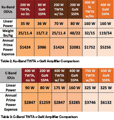
In this case, GaN SSPAs appear to be a good choice under 100 W of linear power. However, when operating at a linear power greater than 100 W, the TWTA becomes the more operating-cost-efficient option. As the power level increases, the TWTA solution becomes more and more compelling.
If the amplifier is to be installed in an enclosed space, such as a room or shelter, the necessity of air conditioning also adds another factor to the cost of ownership of the amplifier.
Heat is the enemy of all electronic parts, regardless of amplifier technology. Unfortunately, amplifier data sheets often do not provide numbers for heat dissipation. Amplifiers that are more efficient will generate less heat and, thereby, require less air conditioning. Also, a system using amplifiers that consume less prime power are going to be cheaper to operate and require a smaller, lower cost UPS and generator power backup system.
Consider The Information Prior To Acquisition
Much has been said regarding the relative merits of KPAs, TWTAs, and SSPAs. It is a fact of modern life that technology evolves, including all types of amplifier technology. Before an informed decision can be made regarding which technology is best for an application, engineers and operators need to make sure they have up-to-date, accurate information about each potential technology solution.
Careful consideration of this information will help eliminate the myths and misinformation present in the marketplace so that they do not lead customers to a sub-optimal and expensive solution. As a supplier of all amplifier technologies, CPI believes there are applications suitable for all technologies, and no one technology fits all applications.
For further information regarding CPI, please visit http://www.cpii.com/satcom