
In 2020, NASA will launch their next exploratory mission to Mars — this mission centers around a nimble, six-wheeled rover that is packed with instruments to search for the evidence of life, assess the climate and geology of the planet, and to prepare for future human exploration.
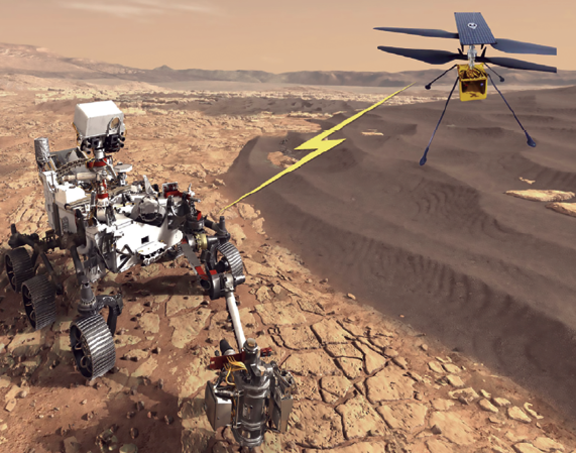
Artistic rendition (Scout Added) is courtesy of NASA/JPL – Caltech.
This robotic explorer is incredibly advanced; however, there is one element the rover cannot do well — plan an ideal route across the rocky terrain. The vehicle’s cameras extend only a few feet into the air, so it can’t see over hills and large rocks.
NASA engineers dreamed up an ingenious solution to this problem: pair the rover with a flying scout that can peer over the terrain. Once per day, an owl-sized helicopter will take flight and photograph the nearby area, sending imagery back to the rover to aid with the route planning. NASA expects these route optimizations to triple the distance the rover is able to cover each day, increasing the vehicle’s opportunity for important discoveries.
But, this innovative plan is fraught with risks and challenges. NASA has never flown a helicopter on Mars, where the atmosphere is a small fraction of the Earth’s air density.
Maintaining a communication channel between the rover and the scout is also difficult. An Ultra-High Frequency (UHF) radio link is the lifeline for imagery, command and control, and relay back to Earth. If this RF link fails, the consequences could be dire: the scout could collide with the rover, fly out of range, or crash and end its usefulness to the mission.

Failure is not an option for this $2 billion mission, so the team at NASA’s Jet Propulsion Laboratory (JPL) is minimizing the risk by running an interesting battery of tests on their RF equipment.
Applying Mars Rover Test Methods to SATCOM
You may well be thinking... “This doesn’t apply to me; what does Mars have in common with the satellite systems orbiting Earth?”
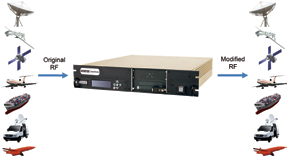
Surprisingly, far more than you may initially believe... the common thread is how to test to assure mission success. In that regard, NASA’s test environment has striking applicability to SATCOM testing on Earth. The foundation of NASA’s testbed is a device called a Channel Simulator. Think of the Channel Simulator as being similar to an RF environment creator. NASA connects the rover and scout radios with the Channel Simulator in between those units (see Figure 1).
This hardware-in-the-loop configuration gives the agency’s engineers flexibility to program in a broad range of RF environments, from normal to worst-case. These include different helicopter flight paths, rover orientation, terrain blockages, and atmospheric conditions — anything that might impact the quality of the communication channel.
They virtually “fly” these scenarios in the lab before they launch such equipment to Mars. This testing ensures the equipment will work and the conditions are quantified that could cause link failure and should be avoided during the mission. Let’s look at four specific test scenarios developed for the Mars mission and explore their utility for SATCOM missions closer to home.
1. Max Separation Between Rover and Scout = SATCOM Receiver Sensitivity
Before sending expensive robots across the solar system, NASA needs to understand just how far the helicopter can fly away from the Rover, while maintaining the communication link. Using the Channel Simulator, NASA engineers can virtually “fly” the helicopter away from the rover to quantify the point where the radios lose their lock.
Channel Simulator configuration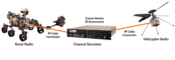
Figure 1. NASA connects the rover and scout radios through the Channel Simulator in a hardware-in-the-loop configuration.Image is courtesy of NASA/JPL—Caltech.
As the distance increases, the received power level of the signal drops due to free space loss, and at some point the radios will not receive enough power to continue operating. This kind of test defines the maximum distance NASA might fly the helicopter during the mission to avoid any communication issues (see Figure 2).
Max separation between Rover and Scout = SATCOM receiver sensitivity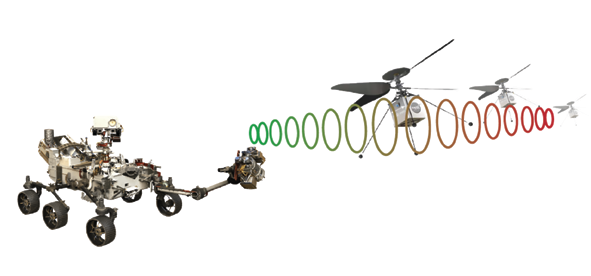
Figure 2. Image is courtesy of NASA/JPL—Caltech.
Any RF Engineers out there? If so, they’ll quickly recognize this as a classic receiver sensitivity test. Sensitivity is a critical metric for any RF system as it determines how much power is required for the receiver to process the information. SATCOM and terrestrial systems on Earth must be characterized for their lowest receive levels — this ensures proper link budgeting, power transmit levels, and maximum distance between transmitters and receivers.
2. Dust Storms on Mars = Atmospheric Conditions on Earth
Mars is a dry planet, and dense clouds of dust can fill the air for weeks at a time. Using the Channel Simulator, NASA can create a virtual dust storm of varying intensity. As the particulate content in the atmosphere increases, the RF signal will experience increasing levels of RF attenuation and multipath scattering. NASA needs to understand how these environmental factors will impact the radio link, using this data to inform decisions about when safe flight is possible (see Figure 3).
Dust storms = atmospheric conditions on Earth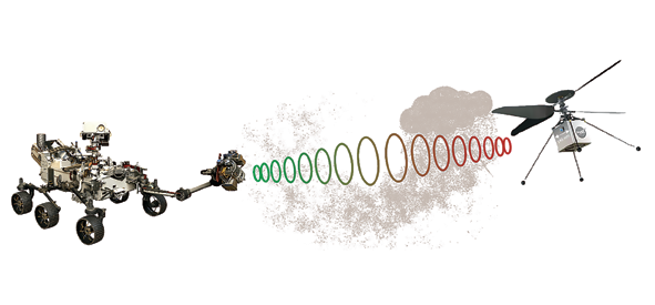
Figure 3. Image is courtesy of NASA / JPL — Caltech.
How does this apply on Earth? Satellite antennas may not operate in a region where dust storms are a threat, but every ground station must account for RF distortions caused by weather. Especially at higher frequencies, rain clouds can chop signal levels by 20 dB or more. Testing satellite communication systems for weather requires dynamic attenuation profiles that accurately reproduce the impact of changing weather conditions.
3. Dynamic Flight Paths on Mars = SATCOM-on-the-Move
The helicopter can follow an infinite number of flight paths, each with its own unique RF distortions. The Channel Simulator helps NASA determine safe parameters of normal flight paths. For example, as the helicopter rotates to different orientations during flight, its communication antenna points in different directions. This pointing angle can have significant impact on the strength of the received signals. Likewise as the helicopter makes maneuvers that change its velocity with respect to the rover, a Doppler shift is imparted onto the RF signal; the receivers must track the changing frequency. Tests such as this help NASA plan safe flight routes that ensure constant communication between the devices (see Figure 4).
Dynamic flight paths on Mars = SATCOM-on-the-Move (SOTM)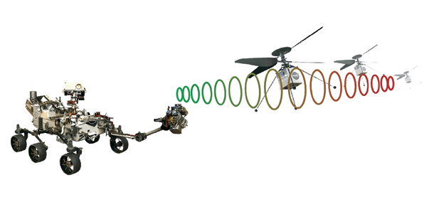
Figure 4. Image is courtesy of NASA/JPL—Caltech.
These RF physics are no different when objects are in motion on Earth. An increasing number of SATCOM applications rely on mobile ground segment equipment, whether mounted to the roof of a Humvee or a commercial airline providing in-flight entertainment (IFE).
SATCOM channels are degraded by banking of the vehicles, shadowing from terrain and man-made structures, and Doppler shift caused by vehicle and satellite motion. These effects degrade the quality of service for users, and Channel Simulators quantify these impacts prior to deployment to enable successful SATCOM-on-the-Move (SOTM).
4. Multipath Fading on Mars = SATCOM in Urban Centers
Lastly, NASA uses their Channel Simulator to recreate the impact of RF energy reflected from the ground or terrain. Imagine the top signal in the image is the primary line-of-sight transmission between the rover and the helicopter. The RF energy is also transmitted out in other directions, and some of the energy reflects off of nearby rocks and terrain. When these reflected signals reach the helicopter, they look like a source of interference that can effectively jam or attenuate the primary signal, an effect called multipath fading. NASA’s Channel Simulator includes a multipath fading module that tests the radios for resilience to this kind of interference (see Figure 5).
Testing for multipath fading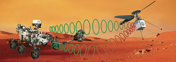
Figure 5. Image is courtesy of NASA /JPL—Caltech.
Many readers have probably experienced multipath fading first-hand. Their GPS receiver has probably lost its position while driving near tall buildings at some point in time. RF signals bounce like pinballs through urban centers, and the GPS receiver is confused by the dozens of duplicate signals that are detected. Multipath fading also affects SATCOM ground stations when the antennas point at low angles relative to the surrounding terrain or water.
Channel Simulators are key to creating these environments before a system is operational, allowing designers to optimize performance and ensure mission success, even in challenging dense urban environments.
Know Before You Go
While the Mars 2020 mission is incredibly unique, the test approaches being used teach a great deal about assuring communication systems on Earth.
Operational testing is always the best way to qualify hardware; however,few have the ability to test live systems under the exact RF conditions of their final deployment. Fortunately, any RF environments can be recreated with the push of a button using Channel Simulators.
Any RF system under development can benefit from this test approach. Consider a maritime traffic control system, relaying voice and position information through satellite; the same RF impacts seen on Mars, like multipath, weather fading, and antenna pointing angles, equally impact seafaring platforms and must be tested.
Likewise, satellite links for in-flight entertainment (IFE) and productivity are becoming ubiquitous on commercial airlines; engineers who build these networks carefully consider how weather, aircraft motion, and satellite coverage impact passenger experience by emulating the RF environment with Channel Simulators.
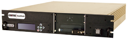
The Kratos Channel Simuilator supports testing for today’s high bandwidth applications.
Plus, the range of military testing applications is virtually endless: surveillance drone communication, satellite TT&C, tactical radios, weapons systems — each of these is deployed into unique and complex RF environments.
NASA has a reputation for innovation and engineering leadership and continues to raise the bar with this creative RF test environment. The lessons gleaned from NASA’s Mars 2020 test bed will help companies to ensure missions on Earth succeed, as well.
HTS, UAVs, Smallsats and the Benefits of Channel Simulation in a Wideband World
Bandwidth requirements continue to grow rapidly with the increase in data volumes, imagery downloads and video streaming for applications such as HTS, smallsats, maritime, aircraft, missiles, and UAVs.
In this new world of increasing bandwidth, the Channel Simulator is a key enabler for growth. Kratos’ Channel Simulator supports high throughput links and addresses new space and connected device trends with testing on many simultaneous channels, highly dynamic channel models, and control that integrates with existing test suites.
The Channel Simulator is able to emulate virtually any of today’s new space and wideband RF environments and tests an RF system’s hardware, software and firmware to determine how they behave under realistic conditions. This can be done in a cost-effective lab environment, rather than a live scenario, where failure isn’t an option.
The Channel Simulator helps overcome these common challenges during RF testing:
• Replicating operational conditions without expensive over-the-air tests
• Creating repeatable, efficient simulations that minimize overall test time
• Ensuring defects are thoroughly flushed out during testing to avoid dangerous problems in the field
• Risking personnel injury or losing high dollar equipment in hazardous RF communication testing conditions
Learn more about how the Channel Simulator can assist your RF mission by viewing additional information at:
www.kratoscomms.com/channelsim
Download the Kratos Channel Simulator white paper at this direct infolink: http://www.kratoscomms.com/channelsim-whitepaper