
Satellite communications (SATCOM) is entering a new era. We are seeing Low Earth Oorbit (LEO) satellite launches accelerating and Geosynchronous Earth Orbit (GEO) satellites continuing to update performance to better connect mobile users.
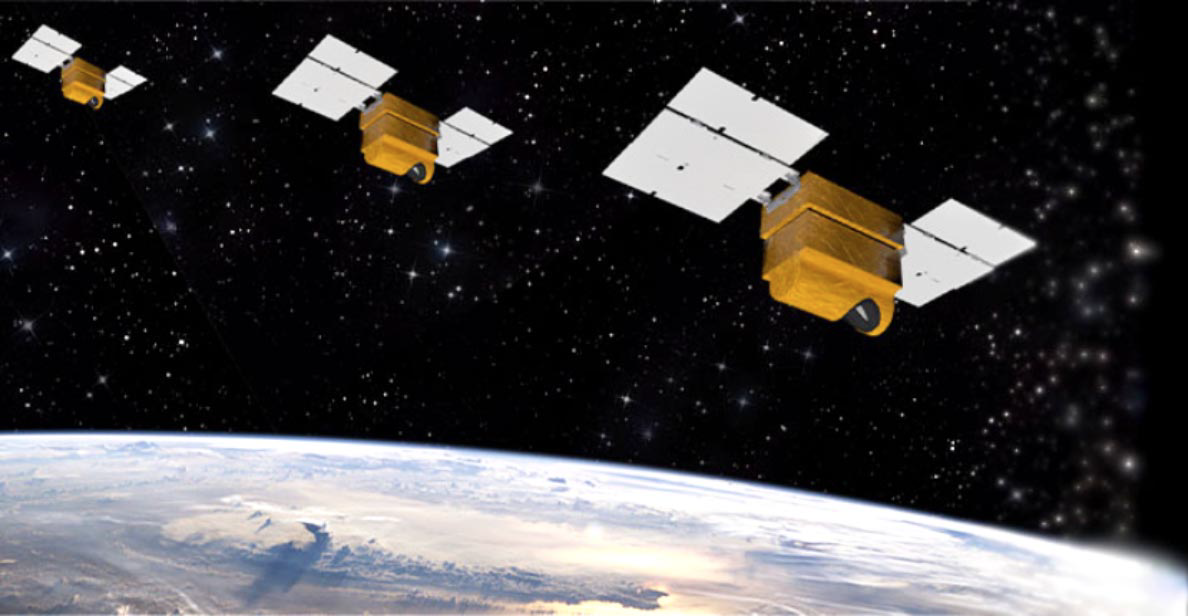
Artistic rendition of satellites on-orbit is courtesy of Ball Aerospace
These new SATCOM systems are enabling new methods of communications to better support the demands of consumer services, media markets, mobility services and government systems. LEO working together with GEO satellites promise to connect the globe with affordable, broadband data communications. While GEO is the SATCOM foundation and continues to be an important part of the mobility market, LEO, with its lower orbits, lower communications latency and global coverage, has the potential to fundamentally change the market.
Until now, a critical technology missing from LEO SATCOM and GEO Mobility SATCOM systems has been affordable and reliable antennas, which enable ground terminals to acquire, track and switch signals between mobile users and rapidly moving LEO satellites. Fortunately, significant advances in Active Electronically Steered Antenna (AESA) systems have made them practical options for both military and commercial SATCOM system applications. By performing fully electronic beam steering, rather than mechanical positioning, such antennas provide the quick steering required for ground stations while also delivering excellent long-term reliability.
A key enabling building-block technology for LEO and GEO AESA systems is the integrated circuits (ICs) that make electronic beam steering possible for active antenna arrays. One IC developer, Anokiwave, has leveraged expertise in silicon (Si) Complementary Metal Oxide Semiconductor (CMOS) IC technology to manufacture a line of microwave/mmW AESA ICs for executing receive and transmit functions in active antenna arrays.
Figure 1.
Collaborating with Ball Aerospace, a provider of phased array antenna solutions for military and commercial markets for more than five decades, Anokiwave’s second-generation of K-, Ka- and Ku-band active antenna ICs have made possible affordable flat-panel fully electronically steerable array antennas.
The antennas are based on Ball’s innovative architecture in which modular antenna building blocks are combined, like Lego pieces, to form larger flat-panel arrays. With no moving parts, the antenna arrays meet various SATCOM regulatory requirements and provide high reliability and performance in terminals for LEO, Medium Earth Orbit (MEO) and GEO satellite systems.
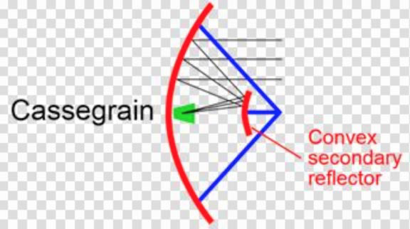
Traditional SATCOM ground-station antennas have been constructed as large reflector “dishes” relying on motorized gimbals for precise
positioning. Configurations such as Cassegrain antennas (graphic above) have relied on the reflective properties of large dish-shaped structures with antenna feed at or behind the surface of the reflector to send and receive beams between satellites.
Alignment of an antenna beam, especially for older analog systems, called for precise mechanical pointing of the antenna to send and receive beams at the best azimuth and elevation with an orbiting satellite to achieve optimum radio performance. Typically, these antenna systems have suffered reduced aperture efficiency due to spill-over loss. The reliability can also be challenging because of the mechanical wear and tear on the motorized gimbal assemblies.
In contrast, in the place of a single antenna feed and dish, an AESA antenna system consists of hundreds — or even thousands — of radiating antenna elements. At each of these elements is attached an active electronic module that performs the antenna beam steering using electronics (phase shifting) in the place of a mechanical moving dish.
These systems are efficient in terms of signal power as they do not have to account for radio frequency (RF) energy loss associated with waveguide signal transmission. They are also much more reliable than mechanically steered systems since there are no motors or moving parts to wear out and the antennas degrade gracefully over time.
Even losing as much as 10 percent of the individual antenna elements in a system will only have a negligible impact on overall antenna performance. System integrators should be aware of some thermal management challenges when using an AESA since power amplifiers are distributed throughout a condensed area on the face of the antenna array to boost signal power.
Fortunately, advanced thermal-management solutions such as advanced materials and cooling structures are available to maintain a safe range of operating temperatures for these antenna arrays for most applications and environmental conditions.
Precisely controlling the signal power and direction (gain and phase) of each antenna element in a phased array is not trivial and is necessary for achieving the desired performance of the array when used in a SATCOM or other system. The antenna elements can be assembled as part of compact printed-circuit-board (PCB) assemblies that occupy much less size and weight as traditional satcom antennas.
The size of a phased-array antenna will depend on the application as well as on the size and efficiency of the individual antenna elements and the number of elements needed to reach the final required antenna performance levels.
Improving Efficiency
To simplify the control of the antenna elements in a phased-array antenna for SATCOM (or other) applications, Anokiwave developed a series of quad-core ICs based on Si CMOS semiconductor technology. Each IC is designed for either transmit or receive functions at different frequencies, including K-, Ka-, and Ku-band frequencies.
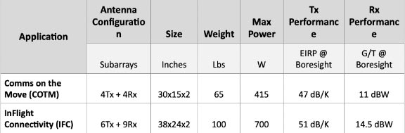 Table 1: Modulare Antenna Size, Weight, Power and Performance.
(Click to enlarge)
For example, model AWMF-0132 accepts K-band signals from 17.7 to 20.2 gigahertz (GHz) from four antenna elements (even when they have dual polarization) and from those four input signals creates a single receive beam over the same frequency range (Figure 1).
By adjusting the gain and phase of the polarized signals from the antenna elements with 5-bit and 6-bit digital control, respectively, the IC can make gain adjustments with a least significant bit (LSB) as fine as 0.5 decibel-(dB) and phase adjustments with a least significant bit (LSB) as fine as 5.625 degrees to enhance the overall receive performance of the phased-array antenna as needed.
The IC runs on only +1.2 V direct current (dc) supply and can achieve as much as 35 dB coherent gain (all four antenna elements combined). The IC features outstanding noise performance for SATCOM receive functions, with a typical noise figure of 2 dB across the frequency range.
On-board temperature compensation helps to minimize the effects of temperature on the quality of the output receive signal beam even over wide temperature ranges, such as -40 to +85°C.
For a SATCOM phased-array antenna designer seeking this same level of control for transmission purposes, the AWMF-0133 from Anokiwave is a quad-core IC that generates four, dual-polarized signals from a single, transmit input feed, from 27.5 to 30.0 GHz. It provides 20 dB gain per antenna element and as much as +8 dBm output power per polarization, or +11 dBm per antenna element when the two polarizations are combined in the far field and also provides telemetry reporting and operates from a +1.2 V dc supply.
At lower frequencies, model AWMF-0146 is a quad-core IC for handling the received signals from four, Ku-band antenna elements. It handles dual-polarized signals from 10.70 to 12.75 GHz from the four elements with high coherent gain (29 dB) and low noise figure (1.9 dB). Model AWMF-0147 supports transmit functions from 13.75 to 14.60 GHz for four dual-polarized antenna elements. It achieves high gain (20 dB) and output power (+12 dBm) per channel and +15 dBm per antenna element. All four of the quad-core ICs are fabricated with a mature Si CMOS semiconductor process. Each is housed in a tiny wafer-level chip-scale package (WLCSP) with electrostatic discharge (ESD) protection on all package pins.
System Design Flexibility
Even with the control and precision offered by these ICs, meeting frequency spectrum regulatory requirements as you steer a beam 360 around the antenna (over the full scan volume), while maximizing the communications link data rates, requires a well-designed antenna.
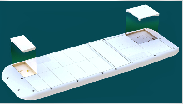 Ball Aerospace SATCOM Phased Array Terminal. Image is courtesy of the company.
As an example, a flat-panel phased array antenna with 2000 radiating elements (1000 transmit and 1000 receive), requires 500 beamforming ICs (assuming one beamforming IC per four antenna elements). The antenna must program the 500 ICs to work together to drive the 2000 elements to create the required transmit and receive beams.
Ball Aerospace has created an antenna architecture that leverages the flexibility provided by the Anokiwave ICs to enable a software-controlled antenna that meets the needs of GEO, LEO and MEO satellites. Ball’s novel approach to the design and production of flat-panel arrays is built upon modular antenna building blocks called subarrays.
Each subarray is environmentally sealed with an aperture integrated radome for reduced cost, increased performance and lowest profile. The size of each subarray has been optimized for frequency band performance, manufacturability and thermal management. The architecture allows independent scaling of transmit and receive antenna sizes and the flexibility to optimize a terminal to the needs of the user without the cost of antenna re-design.
As an example, Ball has developed a SATCOM terminal antenna at Ku-band by using four transmit and four receive subarrays for Communication-On-The-Move (COTM) applications. This antenna is small in size and weight (Table 1) and enables moderate performance to provide users tens of megabit type broadband performance.
When assembled with two more transmit, and five more receive subarrays, the anteanna performance improves, making it a solid solution for In-Flight Connectivity (IFC) SATCOM applications. This size antenna (Table 1) fits onto the top of a plane and enables higher performance, providing a plane of users hundreds of megabit broadband performance.
These antenna opperate over the full Ku-band frequency range, enabling a single Ball antenna to opperate globally. The end user can install one antenna which meets the regulatory requirements of GEO satellites and has the beam mobility to communicate with a LEO satellite.
With a software upgrade, this same antenna can be configured to work with future satellite constellations and waveforms.
www.ball.com/aerospace