
Satellite communications technology has rapidly evolved during recent years, driven by the constant requirement for systems with higher data rates and the uncertain future of classical GEO satellites versus new architectures — HTS (High Throughput Satellites) and VHTS (Very High Throughput Satellites) —- as well as by the mega-constellations in LEO orbits.
Additionally, space exploration continues unabated, with each scientific mission requiring specific communications systems operating in extreme environments. Moreover, now more than ever before, new business formats are being proposed for space in which information and communications systems will be of pivotal importance — now known as New Space.
Given these scenarios, there is a growing demand for high-performance communications systems with lower production and delivery times. Most of these systems require the use of high-gain, reflector-based antennas. Essential to this are the optics of reflectors and feeds capable of handling high powers, working in multiple frequency bands and in dual polarization. The feeds are also responsible for the latest features of the system, which require a high degree of development and technological maturity.
Feeds and Current Capabilities
The current requirements for feeding the reflectors used in GEO satellites demand high illumination efficiency, the most severe requirement being the polarization purity, which often reaches discrimination values between orthogonal polarizations as high as 40dB and 50dB for circular and linear polarizations, respectively.
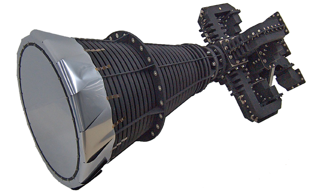 Figure 1.
Given these demanding requirements, as well as the need to handle high powers, the most commonly used radiating elements are horn antennas. Specifically, corrugated horns are used with corrugations perpendicular to the radiation axis, and smooth profiled horns, depending on the bandwidth requirements.
The ability to handle dual polarization is essential, as it allows frequency bands to be reused, thus doubling the communication capacity. Dual polarization operations require including devices capable of distinguishing the polarization before the horn. These are Orthomode Tranducers (OMT) in the case of linear polarization, or more complex polarizing networks for circular polarization.
In addition, problem-free operations in the transmission frequency (Tx) and reception (Rx) bands are now commonplace. This directly halves the number of reflectors, with all the mass, volume and accommodation advantages this entails. This requires including elements to separate and filter the bands in the feed.
Low-pass, high-pass and, recently, bandpass and band-stop filters, are used depending on the band separation and bandwidths. An important aspect is that these filters cannot include tuning elements or moving parts due to the high powers involved.
All of the above leads to sophisticated four-port antenna feeds, one per polarity and per Tx and Rx band. However, the complexity of these devices does not end there, as they must be as compact as possible (the average cost of putting 1 kg. in GEO orbit is estimated to be about $30,000) while also handling power levels that can be as high as thousands of watts. Handling these powers requires considering different limiting factors: multipactor, thermal dissipation and Passive InterModulation (PIM).
Multipactor is a high-power phenomenon that appears in vacuum conditions and that results in an exponential electron avalanche effect due to secondary emissions from metal surfaces. This effect can produce an electric discharge that, in addition to interrupting communications, can permanently damage the antenna. (Figure 1 above: C-band, four-port, antenna feed.)
To prevent this harmful effect, a detailed analysis of the electromagnetic field is of critical importance to minimize the maximum intensity that is produced in the equipment.
As for the thermal limits, the antenna feeds are exposed to the outside of the satellite, with the extreme conditions this entails. They must also dissipate high powers due to ohmic losses that in some cases reach some 40W. It is thus crucial to minimize these losses. This is done by using waveguide technology and by paying special attention during the electrical design of the elements that dissipate the most power, mainly the Tx filters. If necessary, critical parts of the equipment are also silver plated to further reduce losses.
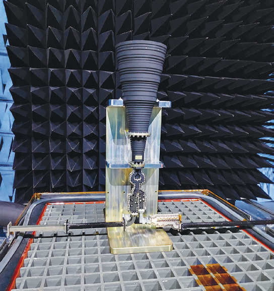 Figure 2. Ku-band feed horn before radiating PIM testing.
A proper thermal design requires protecting the antennas from the severe thermal environment of space, as well as minimizing the power that is delivered to the satellite platform. This is done by using passive elements such as paints (white or black), as well as thermal blankets, Multi/Single Layer Insulators (MLI and SLI).
Finally, one of the most formidable challenges to managing high power is generating low intermodulation products. PIM is a non-linear, high-power phenomenon that occurs in metal-metal junctions and generates a spurious signal that interferes with low-power signals received from the ground.
This parameter is especially critical in the bands where low-order (three or five) products are generated, as is the case of the X- and Ku-bands and, in the near future, Q-/V-bands. Currently, this parameter is mitigated with design rules based on the experimental characterization of previous equipment.
It is also vital that the personnel involved in the manufacturing, inspection, surface treatments and assembly processes of the equipment be highly skilled. PIM should be experimentally characterized at temperatures typically ranging between -50ºC and 110ºC. This requires complex measurement set-ups capable of feeding two Tx carriers and measuring the signal levels in the Rx ports during thermal cycling while the antenna is radiating inside an anechoic chamber.
SENER has developed its own solutions, which take into account all the technological challenges described above and covering the main frequency bands used in satellite communications:
• C-band with Tx: 3.70-4.20 GHz and Rx: 5.925-6.425 GHz.
• X-band for government/military applications with Tx: 7.25-7.75 GHz and Rx: 7.9-8.4 GHz.
• Ku-band typically with Tx: 10.7.12.75 GHz and Rx: 13.75-14.5GHz.
• K/Ka-band Tx: 17.8-20.2 GHz and Rx: 27.5-30 GHz. For government/military use, the assigned bands are Tx: 20.2-21.2 GHz and Rx: 30-31 GHz.
The solutions developed cover all or part of the assigned bands, based on the requirements specific to each satellite. In each case, the performance is optimized as far as possible, depending on the priorities stipulated by the clients.
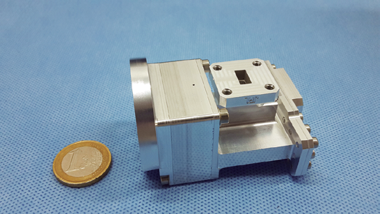 Figure 3. Compact K/Ka-band user feed for multi-beam reflectors.
Requests for dozens of units with short design, manufacturing and measurement turnaround times are increasingly common. In this context, the integrated capabilities and close collaboration between engineering and production is key to implementing high-performance antenna feeds.
Ongoing Developments and Perspectives
The space environment requires the ongoing development of equipment and systems so as to improve current performance and respond quickly to future requests for equipment and systems for eventual applications.
There are numerous, challenging objectives to the development of new high-bandwidth, high-power, compact and low-mass antennas. New frequency bands and new design concepts must also be explored. Moreover, equipment integration and cost reductions must constantly be improved. Given this context, three current developments that cover different areas are described.
C-band ultra-light corrugated horns Even with all the current controversy in the C-band market to allocate part of the spectrum to mobile telephony, there are still many devices in the ground segment of satellite communications that operate in this band. Some of the C-band satellites are reaching the end of their useful life and need to be replaced. Therefore, there is still a demand for feeds in this band, where mass is a highly critical aspect.
A feed with an optimized mass can weigh around 10.5 kg., 8 kg. of which is the horn. Based on previous positive experiences with smooth horns, work is being done to develop corrugated C-band horns by using Carbon Fiber Reinforced Polymer (CFRP). This is expected to reduce the mass of the horns by up to 30 percent while maintaining similar electrical performance.
Feeds for multi-beam antennas The new multi-beam antenna architectures used in HTS and future VHTS rely on horn arrays illuminating a reflector. Each element in the array is a complete feed with all the elements described above, although in this case a distinction is made between the two-port feeds for the user link, with bandwidths of around 1GHz, and the four-port Gateway link, which cover the entire assigned bandwidth.
All these systems work in the K-/Ka-band and the transition to the Q-/V-band is being considered for the Gateway elements, with the assigned bands being Tx: 37.5-42.5 GHz and Rx: 47.2-51.9 GHz. In the case of the K/Ka band, the equipment has to be as compact as possible due to space constraints in the array environment. The Q/V band offers numerous technological challenges, most notably the sensitivity to manufacturing tolerances, integrating extremely small equipment (the WR-19 waveguide is 4.775 x 2.388 mm) and achieving an acceptable level of ohmic losses.
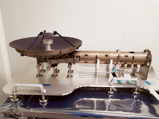 Figure 4. X/Ka-band reflector antenna for deep-space communications.
Compact X-/Ka- reflectors
Deep-space communications with all the probes from the various scientific missions rely on medium- or high-gain reflecting antennas, typically with more than 35 to 40 dBi, on the carrier frequencies assigned within the X- and/or Ka-bands. These antennas have sophisticated steering and pointing mechanisms that are essential to their operation. As a result, the mechanical part of these systems takes on even greater importance.
The reflector requires the use of very compact geometries, such as Cassegrain, Axis-Displaced Ellipse (ADE) or shaped surfaces with low F/D ratios. This compactness results in more electromagnetic interaction between the different elements of the antenna, which translates into greater design complexity. To this we must add operations in a dual frequency band.
Although the usual application of this type of antenna has been deep-space communications, in the near future these systems could also be used for satellite-to-satellite radio links in constellations. This poses a new technological challenge to the mass-scale production of high-performance units.
www.aerospace.sener

Dr. Carlos A. Leal-Sevillano holds a PhD in Telecommunications Engineering from the Universidad Politécnica de Madrid, Spain (2014) and has more than 10 years’ professional experience in the electromagnetic design of high-frequency devices. He is currently a senior electrical engineer at SENER (previously TRYO and RYMSA), in charge of designing advanced antennas and RF equipment for space applications. Prior to joining RYMSA, he worked at the Universidad Politécnica de Madrid and the Universidad Autónoma de Madrid, conducting R&D projects, teaching and contributing as an external consultant to private industry. He was a visiting researcher at the University of Birmingham, UK in 2011 and at NASA’s Jet Propulsion Laboratory, USA in 2012.
Dr. Leal-Sevillano received the Best Student Paper Award of EuCAP 2014, was a finalist at the 25th Anniversary Hispasat Award in 2015, and received the Best PhD Award from the Universidad Politécnica de Madrid in 2016. He has authored or co-authored more than 15 papers in technical journals and more than 30 conference papers. Additionally, he occasionally serves on the technical review board of IEEE journals.
The SENER engineering and technology group has been involved in both the institutional and commercial space sector for more than 50 years. It is currently a top-tier supplier of electromechanical components and systems, communications systems, and navigational (GNC/AOCS), astronomy and space optical systems
SENER’s Aerospace area has around 700 workers and its turnover goes up to 120 million euros. In 2018, SENER acquired TRYO Aerospace & Electronics to reinforce its firm commitment to industry. As a result, the sum of both companies’ capabilities enhances the presence and role of the SENER group in the value chain of the entire onboard communications system, where SENER has traditionally supplied several pointing systems for high- and medium-gain antennas for the ESA’s main science missions (such as BepiColombo, Solar Orbiter, Euclid and Juice), designing, verifying and integrating key communications elements, most notably the antennas or the rotary joints integrated within the mechanisms. Developing these components requires capabilities that extend beyond the field of communications engineering (primarily radio frequency), to include mechanical and thermal engineering.
Today, SENER has the capabilities required to procure complete industrial packages in large programs. SENER is a global leader both in the institutional and commercial space markets, with units and systems successfully launched in over 1,500 satellites and spacecraft for the Telecom market and for NASA, ESA (SENER has become a leading supplier for science programs thanks to its engineering contributions), JAXA and Roscosmos. SENER’s main space missions include the Hubble telescope, the Rosetta probe and the Gaia, MTG, SEOSat / Ingenio, SMOS, Pleiades, Herschel, Planck, IXV, Proba-3, Solar Orbiter, Euclid, Juice, and FLEX satellites, Mars 2020 and the Mars Curiosity rover.