
Since early 2019, the ground mobile network operators (MNO) have initiated the testing and mass deployment of 5G cellular base stations in China and many other countries around the world. The spectrum used by 5G macro cells however overlaps with the extended C-band (3.4-3.7 GHz) which has long been used for the satellite communication services.
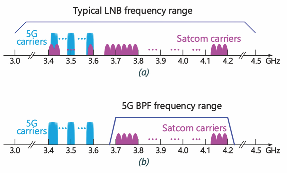 Figure 1. The satellite and 5G carrier frequency ranges in (a) a typical LNB and (b)a 5G rejection BPF.
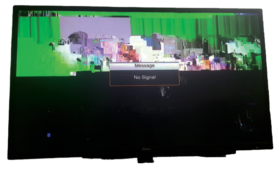
Figure 2. The C-band satellite TV reception affected by 5G interferences.
In some countries, the 5G spectrum even partially or entirely overlaps with the standard C-band (3.7-4.2 GHz) which is also used for Fixed Satellite Service (FSS). AsiaSat has a significant C-band user base over the Asia-Pacific region, and these users may suffer from the widespread deployment of the ground 5G systems in the coming years.
In response to the potential interferences from 5G deployment and to better service our customers, AsiaSat, with its 30 years of experience in satellite user requirement, has collaborated with experienced vendors and launched new models of microwave bandpass filters (BPF) to mitigate the impact from 5G. The BPF can be installed on C-band receiving antennas to reject interfering signals from the adjacent 5G base stations. This paper describes the features of the BPF and its performance in the field tests and at customers’ sites.
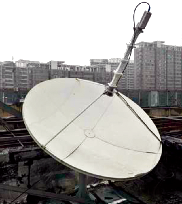
Figure 3. An inefficient ad-hoc filter(s) solution against 5G
interference(photo provided by our customer).
5G Interference Types and the Counter-Measures
A conventional low-noise block downconverter (LNB) in the satellite receiving system has limited frequency selection capability. It can receive, amplify and down-convert the signal ranging from 3.0-4.5 GHz as illustrated in Figure 1(a).
The 5G new radio (NR) carriers to be deployed will mainly reside in the 3.4-3.6 GHz band depending on the regulations and licensing conditions in different countries, which is still within the LNB’s input frequency range. Since the power level of 5G carriers can be much stronger than those received from a GEO communication satellite, it may bring three kinds of interference to the satellite receiving system:
1. The co-channel interference, where the satellite carriers collocated in the 5G carrier band are directly interfered;
2. The adjacent-channel interference, where the satellite carriers in adjacent to the 5G carrier band are worsened by the spectrum regrowth and out-of-band spurious emission from 5G transmissions, and
3. The LNB saturation interference, where the high powered 5G carriers drive the LNB operating point into saturation or the non-linear zone, and the received satellite carriers on the entire C-band are distorted or even power-robbed.
The co-channel interference can only be mitigated by relocating the satellite carriers to the other bands, or by restricting 5G emissions sufficiently lower (e.g., by setting a large no-go zone that surrounds the satellite earth station) than the satellite carriers received on the same band.
The adjacent-channel and LNB saturation are the most prevailing interferences in C-band satellite communications in the standard FSS band. A sample of its consequence is shown in Figure 2, where AsiaSat’s C-band TV channels were interfered by the 5G carriers early this year.
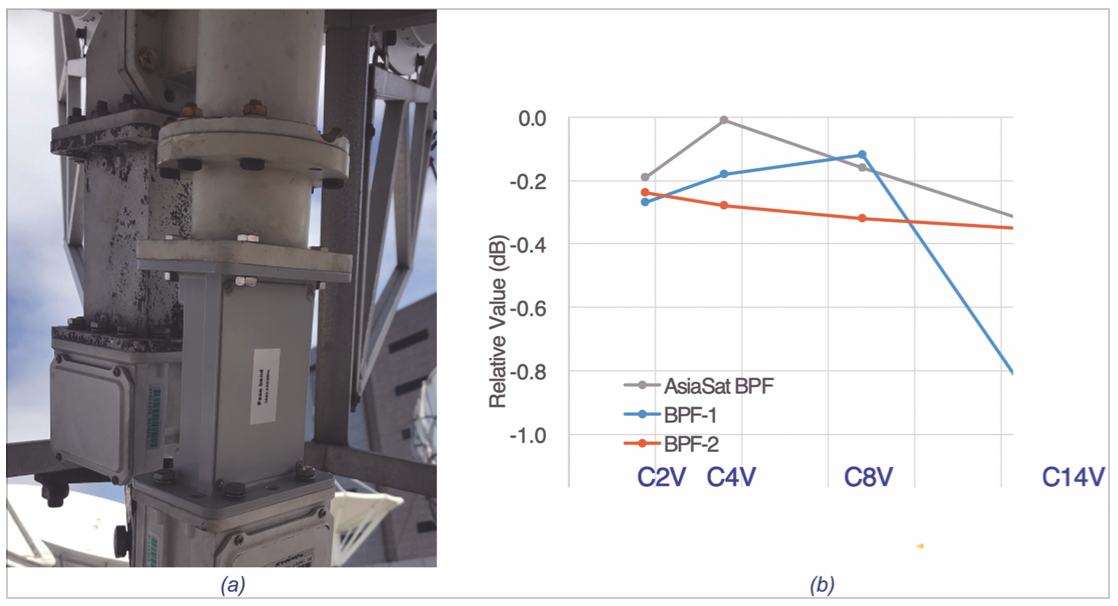
Figure 4. AsiaSat BPF tested in Tai Po, Hong Kong, in conjunction with a 3.7m TVRO antenna. (a) The filter connected in between antenna OMT output and the LNB input, and (b) The tested TV carrier MER degradation over the frequencies and channels.
The satellite service users may have the vague idea of using a rejection filter, but they lack the knowledge in choosing the filters, and thus may result in non-efficient solutions as shown in Figure 3.
An ideal 5G rejection BPF in front of the LNB input can protect the satellite carriers within its passband and isolate the 5G carriers located out of the passband (Figure 1(b)). With the filter, the 5G carriers cannot easily saturate the LNB or worsen it with adjacent-channel emissions.
However, the design and manufacture of a practical BPF is not an easy task. The filter’s passband insertion loss will raise the total noise temperature of the receiving system and erode the link margin, while the out-of-band rejection level determines how far away the satellite earth station can coexist with the 5G base station.
Unfortunately, it is a tradeoff between the filter’s in-band and out-of-band performances: The higher the out-of-band rejection, the worse the in-band insertion loss. Besides, in different countries, the 5G carrier band may also be different. For example, in China (including Hong Kong SAR), it uses 3.4-3.6 GHz band, but in Middle East and some Gulf countries, it can go up to 3.8 GHz.
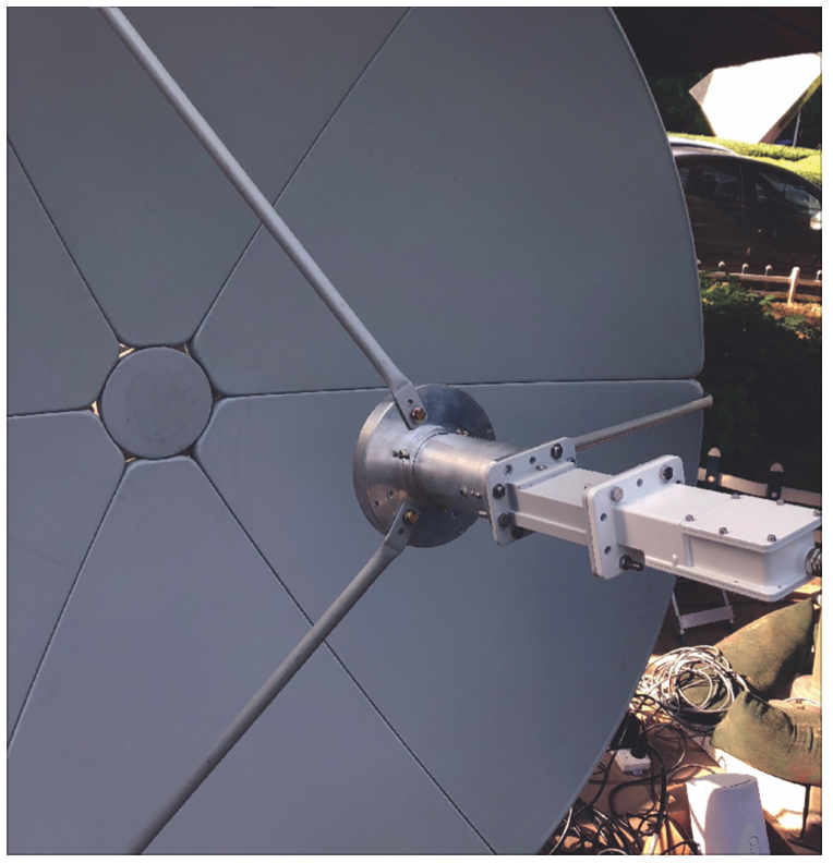
Figure 5. AsiaSat BPF in the field test where
an interfering 5Gbase station (not shown) was
located 90 meters away.
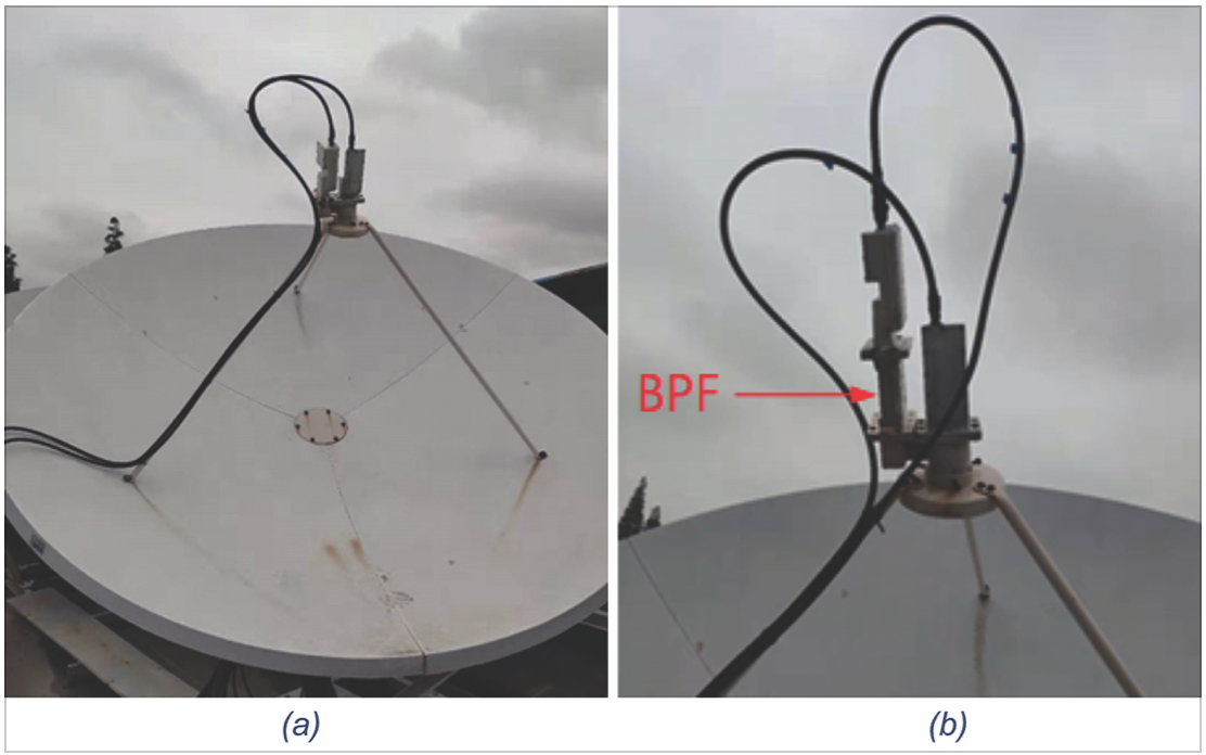
Figure 6. The AsiaSat BPF installed on one polarization of a 2.4m front
feed TVRO antenna: (a) before and (b) after the BPF insatalation.
Performance of AsiaSat’s 5G Interference Rejection BPF
AsiaSat has carefully studied the 5G RF characteristics in different markets, and worked out a series of technical specs for the filter design. The filter concept was then verified with simulations and solid hardware in both the bench tests over different environmental conditions and various field tests with actual antennas and 5G interfering carriers.
The AsiaSat BPF design balances the requirement of both the in-band and out-of-band performances, and is suitable for most victim C-band earth stations, especially for those with limited link margins but have to coexist with a nearby 5G base station.
The unique features of the AsiaSat 5G rejection BPFs include:
• Flexibility: Customized solution for markets with different 5G frequency bands. Unlike the one solution fits all designs, AsiaSat BPF has a series of models with optimized rejection and passband frequencies to reject 5G spectrum nominally ending at 3.6, 3.7 and 3.8 GHz. The rejection level can also be customized in response to the severeness of
the interference and the available link margin.
the interference and the available link margin.
• Performance: Excellent radio frequency (RF) performance on both the in-band and out-of-band. For example, AsiaSat BPF-3700S model can achieve >61 dB rejection over the 3.4-3.6 GHz 5G frequency band and <0.4 dB insertion loss over the 3.7-4.2 GHz FSS passband. The collaborating BPF manufacturer is experienced in cavity and waveguide type of outdoor microwave filters of similar bands.
• Compact Profile & Convenience: With standard WR229 waveguide interface, 12 cm body length and less than 530g mass, it is one of
the shortest and lightest BPFs in
the market.
the shortest and lightest BPFs in
the market.
• Reliability: Warranty time of up to three years. It is the longest in the market, which assures safe use of the BPF products by end users of C-band satellite services.
(a) (b)
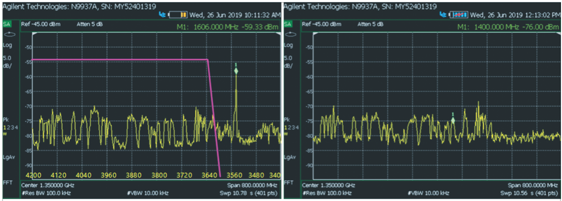
The spectrum comparison (a) before installing AsiaSat BPF and (b) AsiaSat BPF installed. The filter response is illustrated with a pink line in (a).
In addition to the standard bench tests by the vector network analyzer (VNA), the AsiaSat BPF has also gone through different field tests with antennas and satellite RF carriers. In Figure 4(a), it shows the filter was connected to a 3.7m TVRO antenna in AsiaSat’s Tai Po Earth Station for the TV carrier’s modulation error ratio (MER) degradation test. The MER of TV channels ranging from C2V up to C14V of AsiaSat 7 were measured in the test. No 5G signal was involved in this test. Besides the AsiaSat BPF, another two off-the-shelf BPF products were also tested, and the results were normalized against the original no-BPF configuration and shown in Figure 4(b). It can be seen, in general, AsiaSat BPF’s insertion loss brought the least link performance degradation.
Another 5G-SATCOM interference field test was then performed in Beijing. Several BPFs including the AsiaSat BPF were tested with different C-band receiving antennas.
Figure 8. The spectrum comparison (a) before installing AsiaSat BPF (spectrum range 3.4-4.2 GHz), and (b) after AsiaSat BPF installed (spectrum range 3.48-3.78Ghz)
An operating 64T64R 5G base station was located less than 100 m away from the testing earth station antennas. In the test, the 5G active antenna was turned on with fully loaded beam steered towards the testing earth station.
With AsiaSat BPF installed (Figure 5), the 5G interfering carriers received by the LNB were significantly suppressed and the testing earth station system functions well in the normal azimuth and elevation angles to receive the GEO satellite signals.
The Practical Use of AsiaSat BPF at Customers’ Sites
AsiaSat BPFs were intensively tested and proved to work in different satellite Earth stations that suffer from 5G interference. In Figure 6, it shows a 2.4 meter TVRO antenna before and after the AsiaSat BPF installation.
The antenna site is located in Shanghai and was under 5G interference for a time. The spectrum comparison before and after the BPF installation is shown in Figure 7 on the next page. It is observed that the 5G signal peak which used to be 30dB higher than the satellite carriers is now suppressed below the thermal noise floor after AsiaSat BPF is used.
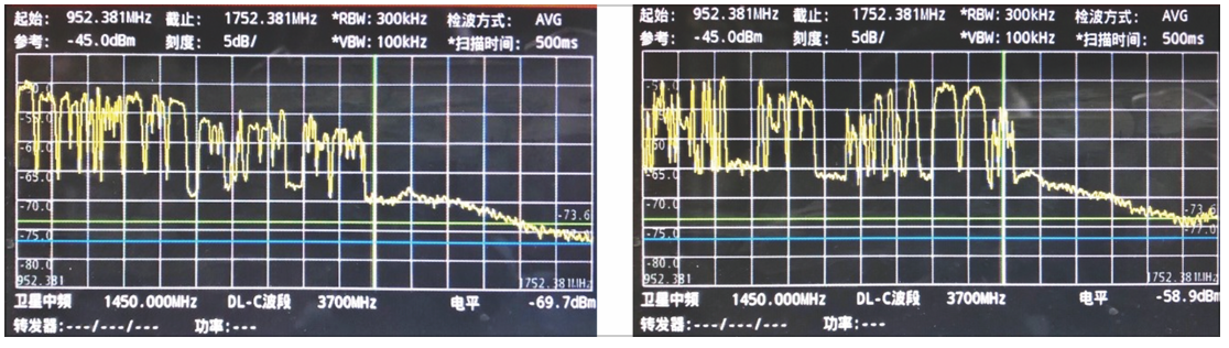
Figure 9. The spectrum plots of other TVRO antennas in the same site after AsiaSat BPFs are installed. No 5G interference is visible in the 3.4-3.6 GHz range anymore.
Another antenna modification and test work was recently completed in Beijing. More than ten AsiaSat BPFs were installed to seven antennas in the customer’s site and excellent 5G signal rejection effect has been achieved.
Before installing the BPFs, the 5G signals are strong and can saturate the customer’s receivers from time to time. To make it worse is that both Mobile Operator A (3.5-3.6 GHz) and Mobile Operator B’s (3.4-3.5 GHz) 5G band signals are picked by the satellite receiving antennas (Figure 8(a).
However, with AsiaSat BPFs installed, all receiving paths of the satellite antennas are clear of 5G interferences as shown in spectrum plots Figure 8(b)) and Figure 9. The antenna feeds with AsiaSat BPFs installed are shown in Figure 10.
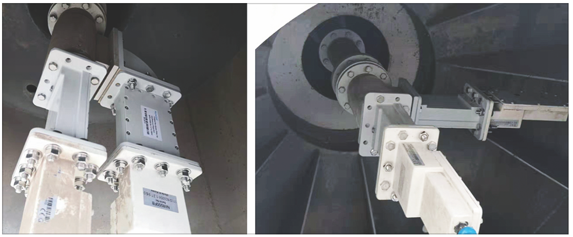
Figure 10. The AsiaSat BPFs installed on two different antenna feeds. Both the V and H-polarization paths are installed with AsiaSat BPFs.
Conclusion
AsiaSat has launched new C-band bandpass filters to deal with the serious interfering challenges from the 5G NR base stations. The BPF has been verified with stringent performance and environmental tests as well as actual field tests with 5G interfering signals.
Test results have shown that the AsiaSat BPF is reliable and effective in protecting the remaining C-band satellite services with interfering carriers on the adjacent bands.
It can be expected that the C-band satellite service users will be benefited from the AsiaSat BPF, and their business can be protected even with the widespread deployment of 5G services.