
AsiaSat has investigated C-band’s exceptionally high rain fade attenuation reported by uplink stations during monsoon seasons in South East Asia — techniques for uplink station operators to mitigate against these issues, to improve their service level availability, are presented in this article.
Three methods are demonstrated to mitigate high rain fade:
1) Replace new feed Teflon coated diaphragm regularly (yearly) to prevent rain water staying on the feed aperture. This is because the waterproof capability of old diaphragm can be degraded after long time operation.
2) Increase the rain blower wind speed as it may help reduce the accumulation of water in front of the feed aperture.
3) Increase the uplink power by 3 dB in advance, an hour before heavy rain begins to compensate resulting decreased power.
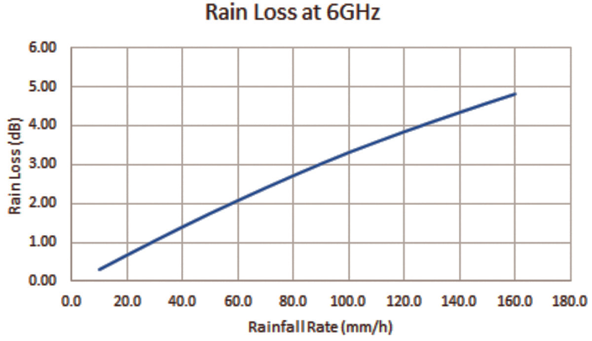 Figure 1. Rain loss versus rainfall rate.
Overview of Uplink Propagation Losses
In satellite transmission modeling, the path loss is the reduction in the power density of an electromagnetic (EM) wave as it propagates through space. The path loss includes free space loss which depends on frequency and distance, and propagation loss as a result of refraction, diffraction, reflection and absorption when the EM wave propagates through the medium between transmitter and receiver. International Telecommunication Union (ITU) provides a model to estimate the propagation loss between earth and space, and is generally used by network engineers to determine the rain margins in the corresponding link budget analysis for different geographical sites.
However, AsiaSat has observed and received reports of higher than expected C-band uplink propagation loss during heavy rain (typically 50mm/h rainfall rate) from some uplink stations. By tracking the performance differences between the satellite telemetry and the rain attenuation prediction data, insight can be gathered for more detailed investigations.
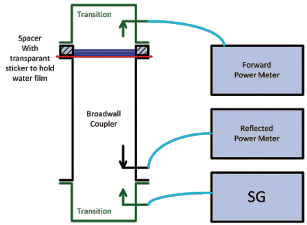 Figure 2. Test setup of signal degradation with respective water film thickness.
For example, it is observed that the uplink propagation loss is about 8 to 11dB through the telemetry for an uplink in Singapore during heavy rain, however the ITU rain model prediction can account for only part of the observed losses based on the reported rainfall rate from Meteorological Service Singapore.
Investigation shows the additional and unexpected loss is a combination of the antenna loss due to the water film formed on the surface of the feed aperture, and the water pool accumulated on the main reflector, resulting in wet antenna attenuation (WAA). Wet antenna attenuation is an additional contributor to the overall signal fading during rain events along the communication link path.
The company performed extensive tests to measure the losses under different water film thickness on the feed aperture. In addition, antenna gain degradation due to the water accumulated on the main reflector surface has been measured. Based on these measurement results, the effect of the wet antenna attenuation from the propagation loss is better understood, and the required transmitting power capability for uplink power control during heavy rain can be estimated.
Wet Antenna Attenuation
The coastal region of China and South East Asia are located within the ITU wet zone. Heavy rain is expected, especially in monsoon seasons. Based on the ITU rain model, the predicted rain loss depends on rainfall rate, antenna elevation, frequency and rain path length. The rain loss is about 4 dB at 6 GHz during severe rain when rainfall rate is greater than 120mm/h. The estimated rain loss of Singapore at 6 GHz versus rainfall rate is shown in Figure 1.
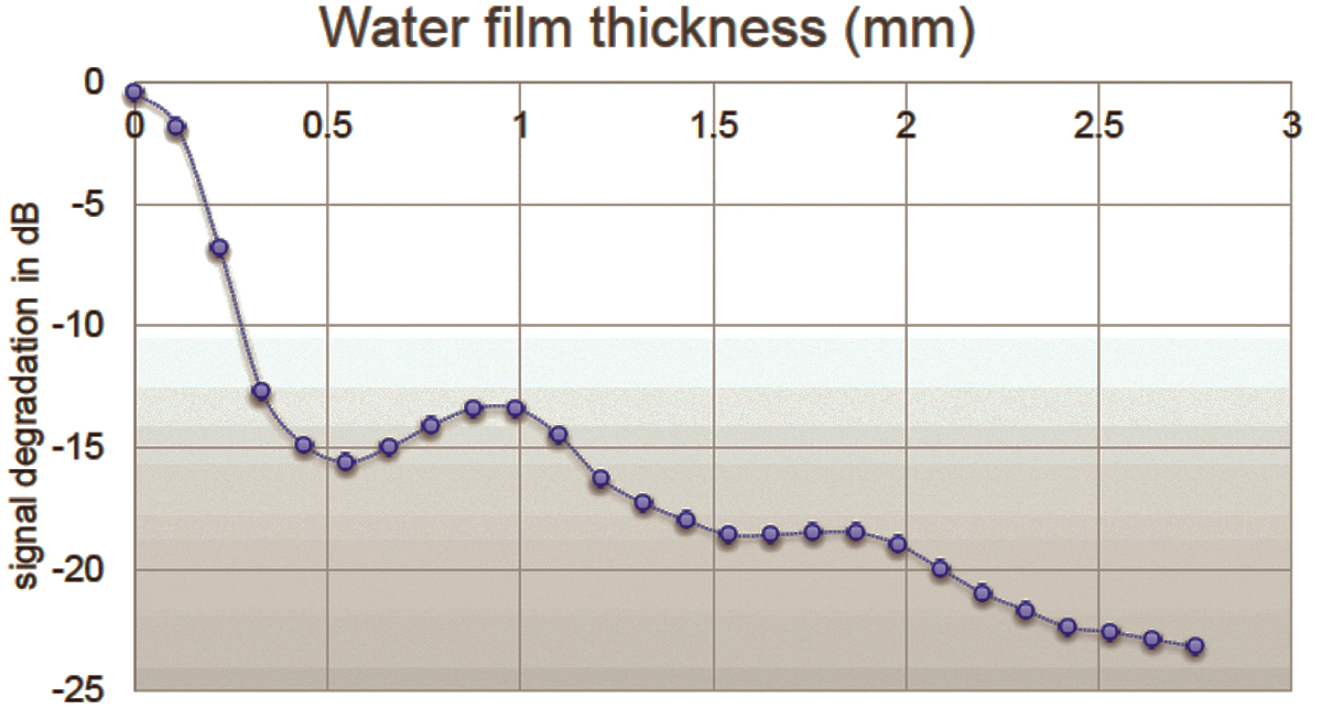 Figure 3. Signal degradation versus water film thickness on a feed aperture
at 6 GHz.
For some advanced satellites, as in AsiaSat’s fleet, uplink power data can be retrieved from satellite telemetry data which measures the input power to the high power amplifier (which is TWTA in AsiaSat’s fleet). By trending the telemetry, the delta of incoming power between clear sky and adverse weather condition from the uplink station can be determined. Based on the trending of the collected data, the uplink rain attenuation was about 8 to 11 dB in Singapore and Hong Kong during heavy rain condition at C-band. By cross correlating it with the ITU data, there is an unexpected additional loss of approximate 6 dB.
AsiaSat knows that wet antenna attenuation can be up to 8 dB for a 0.4 mm water sheet formed on the feed aperture [1]. Wet antenna attenuation could be a function of frequency, antenna structure, material used for the antenna reflector and feed, and the rainfall rate on the antenna. It will affect the antenna efficiency, changes in directivity and variation in antenna feed port reflectivity. The company conducted extensive testing to measure the signal level degradation on antennas with different water film thickness, and different strengths and structures of antenna wetting conditions on the feed aperture and main reflector: the three types are discussed below:
1. Wet feed attenuation with different water film thickness on the feed aperture by using a broadwall coupler.
To investigate the output power degradation on feed aperture with different water film thickness, a broadwall coupler was used to conduct the forward and reflected power measurements. The output signal degradation versus different water film thickness was characterized, and the test setup is shown in Figure 2.
The test results show that the output signal degradation at 6 GHz will worsen when the water film thickness increases. The output signal degradation will be about 2 dB when the water film thickness on the feed aperture is about 0.1mm, but when the thickness reaches 0.2 mm, the output signal degradation will increase significantly to about 7 dB.
The output signal degradation can exceed 11 dB if the water film thickness is more than 0.3 mm. The signal degradation looks higher than the predicted number mentioned in the literature [1] because the assumptions of materials like dielectric constant and conductivity of feed horn radome and permittivity of water used for prediction are different from the actual measurement, particularly when an accurate measurement of the complex permittivity of water is not a trivial effort.
Degradation is caused by part of the transmitting power being reflected back to the transmitter, thus reducing the total output power. The water film on feed will distort the electric field distribution of the feed, and as a result creating a high perturbation on the feed standing wave ratio (SWR) which means more power is reflected. The reflected power will increase as the water film thickness on the feed aperture increases. The relationship between the output signal power degradation and the water film thickness from the measurement data is shown in Figure 3.
2. Signal level drop with different wetting conditions at antenna feed aperture
The wetting conditions on the feed aperture will change from time to time during heavy rain. The water film can fully, partially or thinly cover the feed aperture resulting in different magnitude of degradation. To investigate the corresponding degradation, a wet tissue, a wet towel and a bag of water were placed on the feed aperture to measure the respective degradation. The degradation is obtained by observing the delta of receiving C/N change on a SCPC carrier with detailed test configuration described as follows:
• A modulated carrier was transmitted to our advanced satellite, AsiaSat 7, by a 5m antenna dish under nominal configuration on the antenna feed and the transponder drive is linear.
• The carrier was received by a 9m antenna and an IRD receiver. The receiving carrier C/N can be obtained by IRD receiver and the spectrum analyzer. By observing the changes of receiving carrier C/N with different wetting conditions on the aperture, a better understanding of the wet antenna attenuation was achieved.
• The weather condition under test was clear sky.
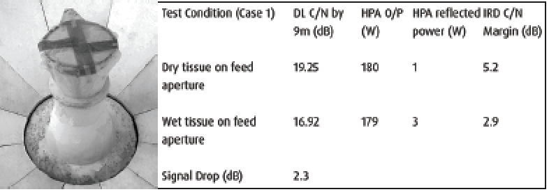 Figure 4a. A wet tissue on feed aperture.
Dry and wet tissue case (Figure 4a.)
• A dry tissue was placed on the feed aperture, the receiving C/N was about 19.3 dB, IRD margin 5.2 dB and HPA reflected power 1W
• A wet tissue was placed on the feed aperture, the receiving C/N was reduced to 16.9 dB, IRD margin 2.9 dB and HPA reflected power 3W.
• By comparing the dry and wet issue case, 2.3 dB signal loss from C/N and 3W HPA reflected power were observed.
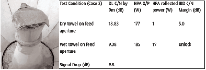 Figure 4b. A wet towel on feed aperture
Dry and wet towel case (Figure 4b.)
• A dry towel was placed on the feed aperture, the receiving C/N was about 18.8 dB, IRD margin 5 dB and HPA reflected power 1W
• A wet towel was placed on the feed aperture, the receiving C/N was reduced to 9.1 dB, IRD margin became unlock and HPA reflected power 19W
• Results show significant signal degradation (i.e., 9.8 dB)
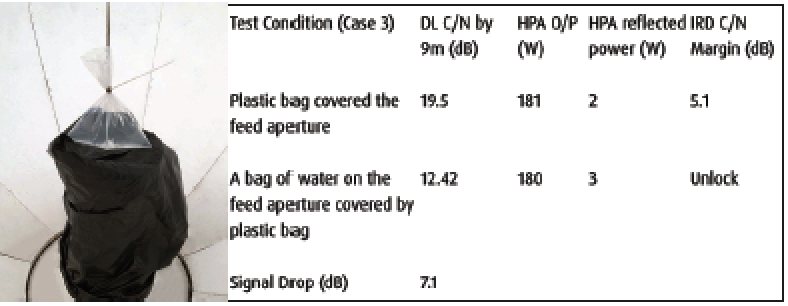 Figure 4c. A bag of water on feed aperture
Plastic bag case (Figure 4c)
• A plastic bag was wrapped around the feed, the receiving C/N was about 19.5 dB, IRD margin 5.1 dB and HPA reflected power 2W
• A bag of water was placed on the feed aperture which was wrapped with plastic bag, the receiving C/N was about 12.4 dB, IRD margin in unlock state and HPA reflected power 3W
• Results show about 7.1 dB signal degradation from the spectrum. The smaller degradation than the wet towel case is because the bag of water is smaller than the feed aperture thus the feed aperture is not entirely covered by the water.
Results show that there is about 2 dB output signal degradation if the water film is as thin as a wet tissue and fully covers the feed aperture. If the water film is like a wet towel and fully covers the feed aperture, it will cause significant degradation on output signal. If the water film does not fully cover the feed aperture, the degradation is less severe so the rain blower does help to mitigate the degradation because it can prevent the water film from staying on the surface of the aperture.
3. Signal level degradation with water pool on main reflector
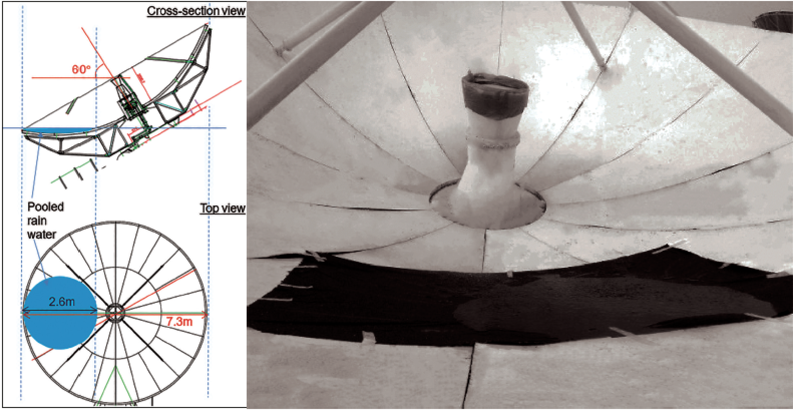 Figure 5. Water pool on main reflector
The antenna gain degrades if water accumulates on the main reflector. To investigate the corresponding loss, a test has been conducted with results in line with our prediction. The antenna elevation look angle toward AsiaSat 7 is about 60 degrees in Hong Kong so the rain water may accumulate on the main reflector.
For a 7.3 meter antenna, the maximum area of water accumulated on the main reflector surface is about 2.6 meters in diameter, which is about 13 percent of the surface area of the antenna. The water pool will affect the total energy toward the target satellite due to scattering, and as a result degrading the antenna efficiency. The estimated worst case gain degradation is about 0.6 dB. The test case has the same test setup as outlined in (2).
A plastic sheet was placed on the main reflector and the receiving C/N was about 19 dB, IRD margin 5.2 dB and HPA reflected power 1W. Water was sprayed on the sub-reflector, with water accumulating on the plastic sheet to form a pool on the 5m antenna.
The observed receiving C/N is about 18.58 dB, IRD margin 4.6 dB and HPA reflected power 2W. It shows about 0.6 dB degradation by comparing the delta of IRD C/N margin which is in line with our prediction. The test setup on feed aperture is shown in Figure 5.
Results and Recommendations
Water film and water pools formed on the feed aperture and on the main reflector due to rain can cause significant output power degradation. The water film on the feed aperture will distort the electric field distribution and cause severe reflected power back to the HPA which degrades the total output power, or may even trip the HPA if the reflected power is larger than the threshold trip point of the HPA. If the water film thickness is 0.2 mm, it will cause 7 dB degradation.
If the water film thickness is greater than 0.3 mm, it will cause more than 11 dB degradation in output power. In addition, the water pool accumulated on the main reflector will affect the antenna efficiency and degrade the antenna gain.
High elevation look angle of the antenna may accumulate even more water on the main reflector and cause more degradation in antenna gain. This explains the extremely high rain attenuation observed during heavy rain in Singapore, the propagation losses include rain loss and additional loss due to water film effect on feed aperture and main reflector. To mitigate the wet antenna attenuation, the following techniques are recommended:
• Replace new feed Teflon coated diaphragm regularly (yearly) to prevent rain water staying on the feed aperture. This is because the waterproof capability of old diaphragm can be degraded after long time operation.
• Increase the rain blower wind speed as it may help reduce the accumulation of water in front of the feed aperture.
• Increase the uplink power by 3 dB in advance, an hour before heavy rain begins to compensate resulting decreased power.
Reference
[1] “Wet Antenna Effect on VSAT Rain Margin” by Jonathan Y.C. Cheah Aug 1993 IEEE