
The Growing Satellite Market
Geostationary (GEO) Systems
With the growing need for ubiquitous connectivity, the satellite communications (SATCOM) industry is poised for explosive growth with multiple high capacity systems either already on-orbit or planned for the near future.

Assaf Toledano, left and
David Corman
There are on-orbit geostationary systems such as ViaSat-1 and ViaSat-2 that offer capacities of 140 and 300 Gbps, respectively. ViaSat-3 has also been recently announced and will offer 1 Tbps capacity which in one satellite will be greater than the rest of the GEO satellite world combined.
Other GEO satellites include Jupiter-1/Echostar-17 and Jupiter-2/Echostar-19 which offer capacities of 100 and 220 Gbps, respectively, with Jupiter-3/Echostar-27 planned to launch in 2021 with a capacity of 500 Gbps.
Low Earth Orbit (LEO) Systems
However, the GEO satellites are not the only ones adding significant capacity to the space industry.

There are multiple LEO satellite systems being designed by companies such as Telesat, OneWeb, SpaceX, Iridium, and LeoSat. These systems have constellations circling the Earth while providing coverage to parts of the planet that have never before received satellite service.
The sizes of these constellations vary from 100’s to 1000’s of satellites, so the aggregate capacity of these constellations will be enormous. Recently, SpaceX/Starlink was approved by the FCC to launch an additional 7,000 internet beaming satellites in addition to the 4,000 that have already been approved by the agency. This will bring a total of 12,000 satellites to that constellation.
These LEO satellites will be in addition to the OneWeb constellation which is planning for approximately 600 more satellites. Telesat will operate 292 LEO satellites with the option to grow to 512 LEO satellites.
Other companies may have similar constellation plans and will be launching satellites, as well. These LEO satellite systems will cover global internet broadband service for individual customers. The plan of these companies is to provide broadband access to millions of potential remote users that do not have access to it today.
Medium Earth Orbit (MEO) Systems
In the MEO systems, one finds O3b which is expanding its constellation of 50 degree latitude equatorial orbit satellites from 16 to 42 in number, with the newer satellites to be deployed in inclined orbits that will provide service to the poles. The firm’s newest seven satellites will offer a combined 10 Tbps of capacity alone.
The Pros and Cons
These different orbit satellite systems will provide full coverage for everyday needs. Each orbit system have their own pros and cons; however, together, they work as a integral system.
The GEO arc is located the farthest from Earth at about 35,800 km directly above the equator and has the advantage of remaining stationary in one position relative to Earth and covers a bigger geographical area with fewer satellites. However, the farther the distance, the longer the latency, and for GEO that latency can be around 600 to 800 msec. This technology is arguably best for TV, radio and weather communications as well as broadcast services.

In comparison, the LEO satellites orbit 500 to 1,500 km from Earth. These satellites are much smaller, cost less to manufacture and to launch. Their life cycle is shorter and, in order to have global coverage, there is a need for many of them on-orbit. These satellites are moving at a much faster pace because of their proximity to Earth and a larger number of them will be required to cover the entire planet.
LEO satellites spend a lot of time over the ocean which makes them less efficient but does provide better communication cover for boats and ships that are far from the shore. Communication with LEO/MEO satellites tend to be more complicated when compared to GEO systems, as the ground stations need to track multiple satellites and switch between satellites during hand-offs.
Another significant advantage for LEO satellites in comparison to the GEO is their latency — their latency is much shorter and measures from 30 to 50 msec and that makes it very attractive to gaming, video streaming, audio and fast internet communications.
The MEO satellites orbit above the Earth at about 5000 to 12000 km altitude with latencies of 125 to 250 msec which make them very good for GPS use and for services that can tolerate moderate propagation delays.
This huge amount of capacity will give rise to unprecedented numbers of user terminals, most of which must have steerable antenna technology. Steerable antennas are required when either the satellite or the satellite terminal is in motion.
Thus, LEO and MEO systems require steerable antennas for both fixed and mobile users. Similarly, GEO systems require steerable antennas for mobile users or even for auto-pointing applications where the antenna beam can self-point at a GEO satellite for the highest throughput performance.
Traditionally global high-capacity satellite bands operate at 10.7 to 12.75 GHz or 17.7 to 20.2 GHz on the downlinks, and 13.75 to 14.5 GHz and 27.5 to 30.0 GHz on the uplinks. How can the satellite industry mass produce high frequency active antennas with steerable beams in sufficient volumes to leverage the significant space resources being deployed?
What is needed are antennas that are high performance, low profile, manufacturable using only 2D manufacturing methods, scalable in size to meet the various use cases from large, high throughput terminals to smaller, and lower throughput terminals.
The Electronically Steered Active Phased Array Antennas in SATCOM
Phased array antennas can solve many of the challenges presented above — phased array antennas are an array of radiating elements that are fed varying phase and amplitude information to form a beam in a given direction. The beam is steered electronically with no moving parts. Without the need for bulky mechanical gimbals, this genre of antenna is smaller, more reliable, and less costly
to maintain.
For highest performance in any radio system, the power amplifier and low noise amplifier need to be placed as close to the antenna as possible to minimize front end feed loss. In phased array antennas, this means that the Tx/Rx plus beam steering functions need to be placed right at the radiating element.
As the distance between radiating elements in the array (the lattice) is typically one-half wavelength, this means the real estate available for the phased array antenna electronics is quite limited, especially at higher frequencies where the wavelengths are very short. The only monolithic technology that can provide sufficient integration of the requisite RF, analog, and digital functions is silicon. Fortunately, Moore’s Law has allowed silicon to advance to the point where III-V semiconductor components such as GaAs are no longer needed in the array resulting in major cost savings and simpler construction.
Typical construction of a planar phased array is to use a multi-layer printed circuit board (PCB) with antenna elements printed in metal on one side of the PCB and the silicon control electronics on the opposite side of the board. Inner layers of the PCB provide beam-forming networks, DC (direct current) voltage, and control signal routing.
This type of construction allows simple surface mount assembly using pick and place machines and IR reflow. It is important to have optimized layout from matching, loss and power perspective to achieve the best performance. Anokiwave’s products are designed to enable optimized layout with minimum board cost and complexity.
Planar phased array antennas are scalable in size and allow larger antennas to support higher G/T or EIRP applications and smaller antennas to support lower G/T or EIRP applications. The silicon ICs that reside within the antenna lattice are just stepped and repeated across the array regardless of the size of the array.
Anokiwave ICs Enabling the NexGen of Active Phased Array Flat Panels
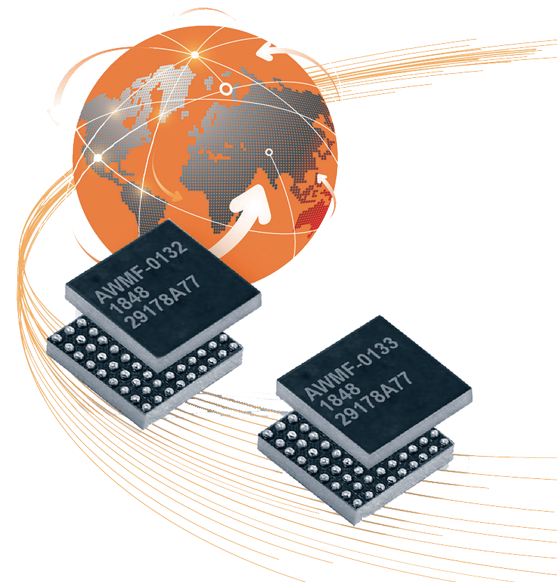
Anokiwave recently announced their second generation of SATCOM ICs designed specifically for high volume, low cost phased array terminals as described herein. These parts are designed for FDD (Frequency Division Duplex) operation covering global SATCOM Ku-, K-, and Ka-bands.
Each IC in the family supports four, dual polarization radiating elements with full polarization flexibility. Each channel has its own individual control of phase and gain for maximum flexibility. The gain control per element also allows the customers to adjust the gain per element to achieve a desired side lobe level. There is also power detector circuitry with an ADC (Analog to Digital Converter) on each TX element to provide an estimate of transmit output power. These ICs operate from a single supply of 1.2v and offer high gain, low noise figure, and excellent DC efficiency.
Additional features include gain compensation over temperature, temperature reporting and zero calibration for the array. All of these features come in a small package of 4.4 x 3.6 mm WLCSP (Wafer Level Chip Scale Package) for easy installation in planar phased array antennas.
Anokiwave’s zero calibration (ZERO-CAL®) technology removes the need for array calibration and that reduces customer test time, complexity and cost. The ICs also offer fast beam steering to enable rapid angular tracking in mobile environments and fast beam hand-offs between LEO/MEO satellites. The temperature compensation is designed to allow constant gain performance over the full range of temperature range of -40 degC to +85 degC. The ICs provide telemetry to the host system and enable pro-active maintenance by the system operator reducing expensive truck rolls.
Finally, Anokiwave’s SATCOM ICs use 300 mm CMOS Silicon to ensure the perfect combination of performance and low cost that truly make commercialization of Active Electronically Steered Antennas for SATCOM a reality.
Conclusion
Anokiwave is the only company today providing ICs in every mmWave 5G, SATCOM and Radar band, thereby ensuring maximum economies of scale for true low cost and high-performance flat panel solutions.
With the firm’s new K-/Ka-band Gen 2 SATCOM ICs, Anokiwave is setting the benchmarks for high performance and low cost flat panel antennas for mass commercial deployment for LEO, MEO and GEO SATCOM ground terminals and Satellite-On-The-Move (SOTM) applications.
www.anokiwave.com